Antenna with eight modes

A mode and antenna technology, applied in the direction of antenna, antenna grounding switch structure connection, radiating element structure form, etc., can solve the problems of difficulty in reducing the size of the antenna array module and increasing the manufacturing cost, and achieve remarkable effects and high industrial application value. Effect

Inactive Publication Date: 2019-11-19
CHANGSHU HONGBO COMM TECH CO LTD
View PDF6 Cites 1 Cited by
  • Summary
  • Abstract
  • Description
  • Claims
  • Application Information

AI Technical Summary

Problems solved by technology

Furthermore, especially in the case of current electronic devices that require light, thin, and small antennas, the area of ​​the circuit fed into the network may be larger than the antenna array, making it difficult to reduce the overall size of the antenna array module, making it difficult to reduce the overall size of the antenna array module. Substantial increase in the manufacturing cost of antenna products

Method used


Image

  • Antenna with eight modes
  • Antenna with eight modes
  • Antenna with eight modes

Examples


Embodiment Construction

[0035] The present invention will be further described below in conjunction with the examples, but not as a limitation of the present invention.

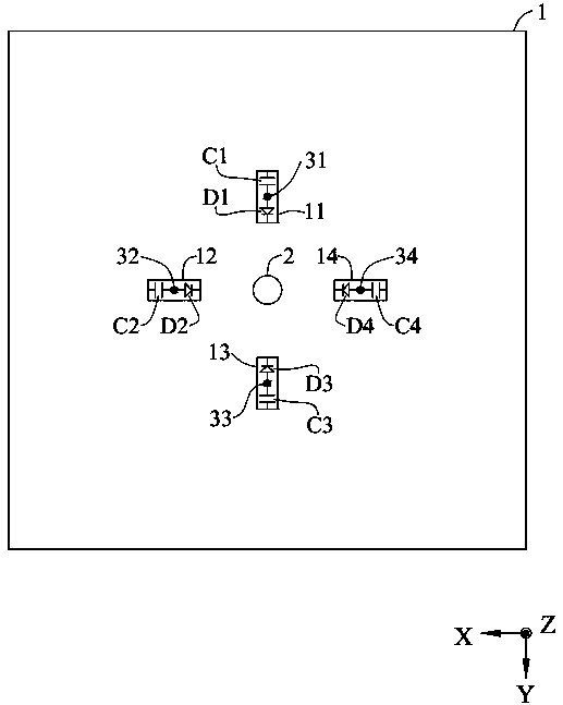
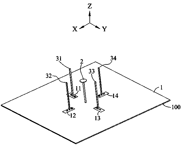
[0036] Please refer to figure 1 and figure 2 , figure 1 is a schematic plan view of the ground plane of the eight-mode antenna provided by the embodiment of the present invention, figure 2It is a schematic diagram of the structure of the eight-mode antenna provided by the embodiment of the present invention. The antenna with eight modes includes a ground plane 1 , an omnidirectional antenna 2 , a first parasitic element 31 , a second parasitic element 32 , a third parasitic element 33 and a fourth parasitic element 34 . The omnidirectional antenna 2 is erected on the ground plane 1 to excite the omnidirectional radiation pattern, and its feed is set between the omnidirectional antenna 2 and the ground plane 1 . The first parasitic element 31 is erected on the first opening area 11 of the ground plane 1, the first opening area ...


PUM

PropertyMeasurementUnit
Lengthaaaaaaaaaa
Lengthaaaaaaaaaa

Abstract

The invention discloses an antenna with eight modes. The antenna comprises a ground plane, an omnidirectional antenna, a first parasitic element, a second parasitic element, a third parasitic elementand a fourth parasitic element. The first parasitic element, the second parasitic element, the third parasitic element and the fourth parasitic element are symmetrically erected around the omnidirectional antenna with the omnidirectional antenna as the center. The first parasitic element is connected with the ground plane through a first capacitor and is conducted with the ground plane through a conducted first diode so as to shorten a grounding path. The second parasitic element is connected with the ground plane through the second capacitor and is conducted with the ground plane through theconducted second diode so as to shorten the grounding path. The third parasitic element is connected with the ground plane through a third capacitor and is conducted with the ground plane through a conducted third diode so as to shorten a grounding path. The fourth parasitic element is connected with the ground plane through a fourth capacitor and is conducted with the ground plane through a conducted fourth diode so as to shorten a grounding path. The conduction states of the diodes are used for controlling the generation of eight modes.

Description

technical field [0001] The invention relates to an antenna, especially an antenna with eight modes. Background technique [0002] The radiation pattern of the antenna varies according to the basic working principle of the antenna. Various radiation patterns have different applications. For example, the omnidirectional radiation pattern is suitable for the terminal device so that the terminal device can receive wireless signals from all directions. Signal. For another example, base station antennas, such as wireless access point antennas, may need to be able to generate radiation patterns in specific directions, so as to perform wireless communication with terminal devices located in various specific locations. [0003] Generally speaking, although an array antenna can be used to control a specific radiation pattern, the control circuit of the array antenna (including switches, phase control, and feeding network, etc.) introduces more problems of transmission loss. Furtherm...

Claims


Application Information

Patent Timeline
IPC IPC(8): H01Q1/36H01Q1/50H01Q19/30
CPCH01Q1/36H01Q1/50H01Q19/30
Inventor 施佑霖张家豪杜昆谚曾国祯颜红方李荣耀
Owner CHANGSHU HONGBO COMM TECH CO LTD
Why Eureka
Try Eureka