ZOOM cutting device for adjustable ring light spot based on aspheric mirror, and method

An aspherical mirror and annular spot technology, applied in optics, optical components, laser welding equipment, etc., can solve the problem that a single axicon lens cannot achieve adjustable annular spot, which is not conducive to the process optimization of plates with different thicknesses, and increases the difficulty of mechanical design and control. and other problems, to achieve the effects of controllable mechanical design and control difficulty, continuous adjustment of pitch and thickness, and novel structural design

Inactive Publication Date: 2019-11-19
SHANGHAI EMPOWER AUTOMATION TECH CO LTD
View PDF0 Cites 3 Cited by
  • Summary
  • Abstract
  • Description
  • Claims
  • Application Information

AI Technical Summary

Problems solved by technology

The single-piece axicon lens cannot realize the adjustable annular spot, which is not conducive to the process optimization of plates with different thicknesses; the HighYAG free-form surface lens group needs to be adjusted with a double-piece free-form surface lens group, and additionally requires the movement of the collimator or focusing lens to compensate for the focus The position increases the difficulty of mechanical design and control, and the mirror surface processing is very difficult; the Precitec micro-lens group can realize the adjustment of the energy ratio from a solid spot to a fixed-diameter annular spot, and there is also the problem of non-adjustable diameter, while the single-chip micro-lens solution is reduced. The number of lenses reduces the cost, but the diameter cannot be adjusted, the focus spot is circular, and it is impossible to perforate, so the lens needs to be constantly switched during the cutting process

Method used


Image

  • ZOOM cutting device for adjustable ring light spot based on aspheric mirror, and method
  • ZOOM cutting device for adjustable ring light spot based on aspheric mirror, and method
  • ZOOM cutting device for adjustable ring light spot based on aspheric mirror, and method

Examples


Embodiment Construction

[0031] The following will clearly and completely describe the technical solutions in the embodiments of the present invention with reference to the accompanying drawings in the embodiments of the present invention. Obviously, the described embodiments are only some, not all, embodiments of the present invention. Based on the embodiments of the present invention, all other embodiments obtained by persons of ordinary skill in the art without making creative efforts belong to the protection scope of the present invention.

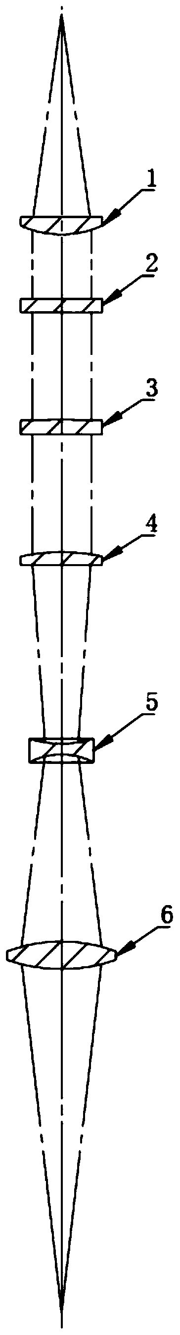
[0032] see figure 1 , the present invention provides a technical solution: an adjustable annular spot ZOOM cutting device based on an aspheric mirror, including an aspheric collimating mirror 1, a first curved axicon lens 2, a second curved axicon lens 3, an aspherical focusing mirror 4, Double-concave aspheric mirror 5 and double-convex aspheric mirror 6; aspheric collimating mirror 1, first curved axicon lens 2, second curved axicon lens 3, aspheric focusing...


PUM


Abstract

The invention discloses a ZOOM cutting device for an adjustable ring light spot based on an aspheric mirror, and a method. The device includes an aspheric collimating mirror, a first curved cone lens,a second curved cone lens, an aspheric focusing mirror, a double concave aspheric mirror, and a double convex aspheric mirror. A structure design of the device is novel; characteristics of a ring light spot are achieved based on an axicon lens; compensation characteristics of the size of a focusing light spot, a light beam divergence angle and a focus position are achieved based on a ZOOM opticalsystem; based on characteristics of positive and negative defocus cutting processes of medium and thick boards of different materials, through a mode of moving one of curved cone lenses along a lightbeam transmission axis, and through combination of cooperative adjustment of the ZOOM optical system, a divergence angle of a focused light beam, the size of a focus solid light spot, a solid lightspot to the ring light spot, and the diameter and thickness of the ring light spot are continuously adjustable; and at the same time, based on the need of a laser cutting process, circular energy distribution corresponding to a defocused light beam segment is achieved, and the cutting speed, the section quality, the cutting thickness, and the section verticality of the boards can be greatly improved.

Description

technical field [0001] The invention relates to the technical field of fiber laser cutting, in particular to a ZOOM cutting device and method based on an aspheric mirror-based adjustable annular spot. Background technique [0002] Due to the advantages of high electro-optical conversion efficiency, good fiber flexibility, high coupling efficiency, and good beam quality, as well as the emergence of high-power lasers, fiber lasers have made their market share increasingly prominent. At present, fiber-coupled output lasers of kilowatt level are quite popular. Watt-level lasers are gradually released to the market, making fiber laser processing more and more common. [0003] The laser cutting application of fiber laser covers various metal processing markets such as stainless steel, carbon steel, aluminum, copper, etc. With the increase of laser power, the cutting thickness of plates of different materials becomes thicker. [0004] As we all know, although the conventional aber...

Claims


Application Information

Patent Timeline
IPC IPC(8): G02B27/09B23K26/064B23K26/38
CPCB23K26/064B23K26/0648B23K26/38G02B27/0955
Inventor 邵华江李思佳
Owner SHANGHAI EMPOWER AUTOMATION TECH CO LTD
Why Eureka
Try Eureka