A Different Speed ​​Double Electron Injection Gun

An electron injection and electron gun technology, which is applied to the discharge tube electron gun, the electron/ion gun of the transit time type electron tube, the transit time type electron tube, etc. , the effect of reducing the size and reducing the current density

Active Publication Date: 2020-11-13
UNIV OF ELECTRONICS SCI & TECH OF CHINA
View PDF4 Cites 0 Cited by
  • Summary
  • Abstract
  • Description
  • Claims
  • Application Information

AI Technical Summary

Problems solved by technology

However, the existing electron guns are usually designed to emit a single electron beam or multiple electron beams with the same velocity, and no design scheme for an electron gun capable of emitting electron beams with different velocities has been found.

Method used


Image

  • A Different Speed ​​Double Electron Injection Gun
  • A Different Speed ​​Double Electron Injection Gun

Examples


Embodiment Construction

[0019] In order to facilitate those skilled in the art to understand the technical content of the present invention, the content of the present invention will be further explained below in conjunction with the accompanying drawings.

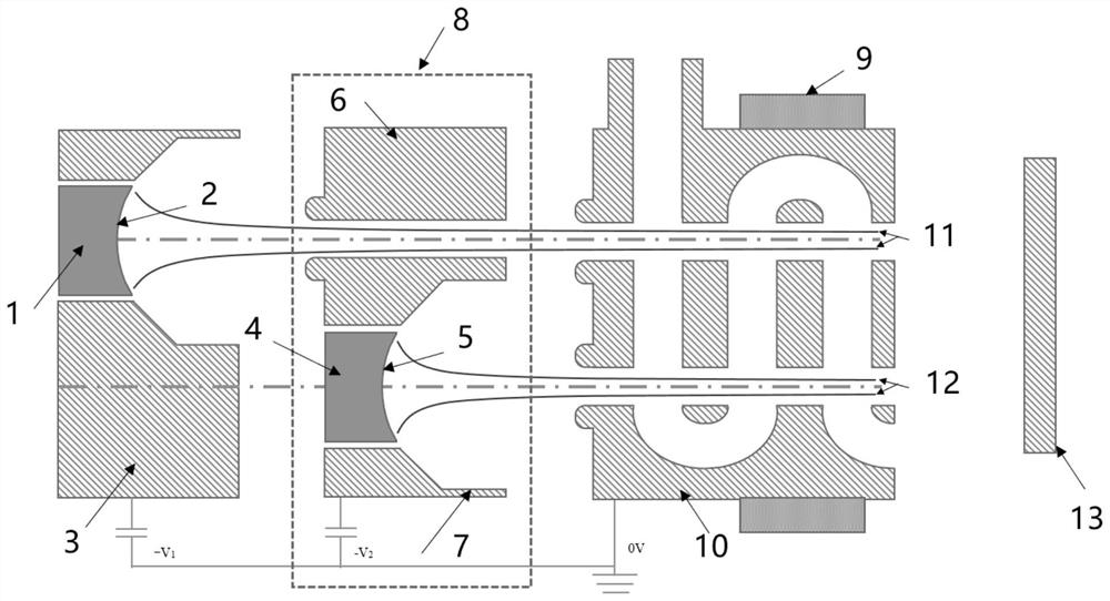
[0020] Such as figure 1 Shown is a different-speed electron injection gun of the present invention, including two electron injection channels, which are denoted as the first electron injection channel 11 and the second electron injection channel 12, and also sequentially include: a first cathode 1, a cathode-anode hybrid structure 8. The high-frequency system including the second anode 10 and the collector 13, the first electron beam emitted by the first cathode emitting surface 2 is transmitted along the first electron beam channel 11, and the first electron beam first passes through the first cathode 1 and the first electron beam. The voltage difference between the cathode and anode hybrid structure 8 is accelerated for the first time, and then...


PUM


Abstract

The invention discloses an electron injection gun with different speeds, which is applied in the field of vacuum electron technology. In order to solve the problem that the existing technology cannot solve the problem of emitting electron injection guns with different speeds; the invention adopts the high potential function of the anode and the electron injection gun with the cathode. The cathode-anode mixed structure with emission function, through the voltage difference between the first cathode and the cathode-anode mixed structure, the first electron beam emitted by the first cathode emitting surface is accelerated for the first time, and through the connection between the cathode-anode mixed structure and the second anode The voltage difference between the first electron beam is accelerated for the second time; the second electron beam emitted by the cathode-emitting surface on the cathode-anode hybrid structure is accelerated once by the voltage difference between the cathode-anode hybrid structure and the second anode, and the second electron beam is accelerated by The first focusing pole focuses on the first electron beam, and the second focusing pole focuses on the second electron beam, so that two high-quality electron beams can be emitted at different speeds.

Description

technical field [0001] The invention belongs to the technical field of vacuum electrons, and in particular relates to a different-speed double-electron injection electron gun. Background technique [0002] Compared with solid-state devices, high-power, high-stability, and long-life vacuum devices have great advantages and development potential in the millimeter-wave terahertz band. However, with the development of vacuum electronic devices to higher frequencies, the size of the structure is reduced, and the difficulty of processing and assembly is greatly increased. In order to open up the development of vacuum devices in the terahertz field, the design of new slow-wave structures (such as interleaved double-grid slow-wave structures, double-row metal comb-shaped slow-wave structures, and folded waveguide-like slow-wave structures) and the new injection-wave interaction The exploration of the mechanism of action has become the research focus of terahertz vacuum devices in r...

Claims


Application Information

Patent Timeline
Patent Type & Authority Patents(China)
IPC IPC(8): H01J3/02H01J23/06H01J23/02H01J23/08
CPCH01J3/02H01J23/02H01J23/06H01J23/08
Inventor 高鸾凤胡玉禄胡权朱小芳杨中海李斌
Owner UNIV OF ELECTRONICS SCI & TECH OF CHINA
Why Eureka
Try Eureka