Finished product warehouse discharging and transferring device

A transfer device, finished product warehouse technology, applied in the directions of transportation and packaging, packaging, loading/unloading, etc., can solve the problems of segregation, tedious vehicle operation, difficult to grasp the discharge amount of the finished product warehouse, etc., to achieve accurate discharge, reduce segregation, Easy to use effect

Pending Publication Date: 2019-11-12
陕西达刚筑路环保设备有限公司
View PDF0 Cites 1 Cited by
  • Summary
  • Abstract
  • Description
  • Claims
  • Application Information

AI Technical Summary

Problems solved by technology

[0004] The main purpose of the present invention is to solve the problems in the prior art that it is difficult to control the discharge amount caused by the direct discharge of the finished product warehouse to the receiving vehicle, and the cumbersome operation caused by the frequent movement of the vehicle. High occurrence of segregation, and the technical problems that the movement of the receiving vehicle is limited by the environmental space, and a finished product warehouse discharge and transfer device is provided

Method used


Image

  • Finished product warehouse discharging and transferring device
  • Finished product warehouse discharging and transferring device
  • Finished product warehouse discharging and transferring device

Examples


Embodiment 1

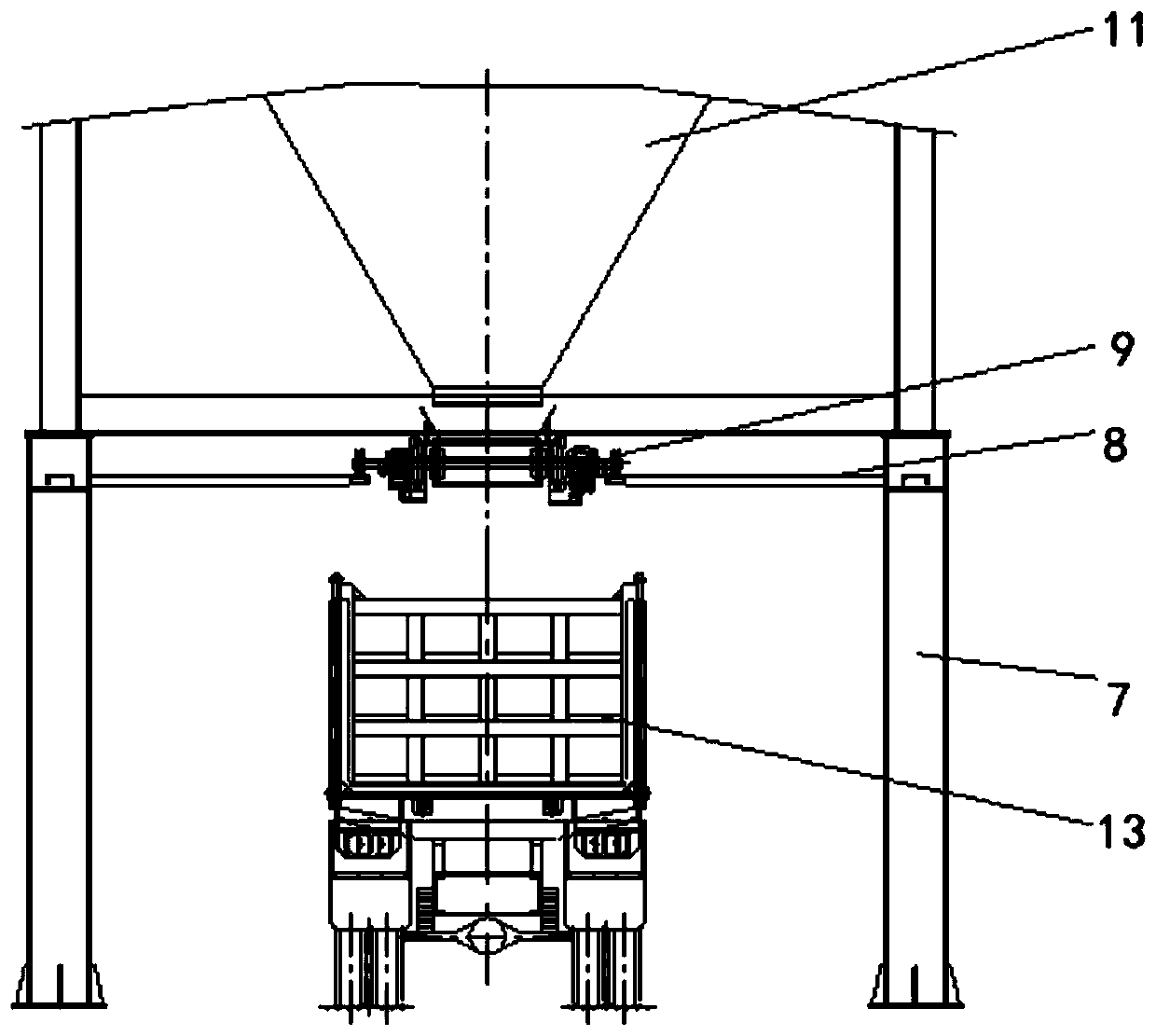
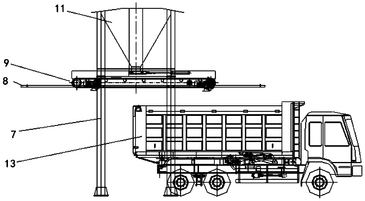
[0034] Such as Figure 1 to Figure 6 , a finished product bin discharge transfer device, including a first driver 6, a bracket 7, a rail 8 and a transmission mechanism 9; the rail 8 is fixed on the bracket 7; a sliding assembly is fixed on the transmission mechanism 9, and the sliding assembly and The rails 8 are matched; the transmission mechanism 9 is located directly below the finished product bin 11; the output end of the first driver 6 is connected with the slide assembly. Wherein, the transmission mechanism 9 includes a scraper 1, a material receiving plate 4, a second driver 3, a mounting frame 2, and a driving shaft 501 and at least one driven shaft 502 installed in parallel on the mounting frame 2; the driving shaft 501 Both ends of the driven shaft 502 and the driven shaft 502 are provided with a sprocket 503, and the sprocket 503 on the same side is covered with a chain 504, and the driving shaft 501 is coaxially fixedly connected with the output shaft of the second...

Embodiment 2

[0037] Such as Figure 1 to Figure 3 ,as well as Figure 7 , a finished product bin discharge transfer device, including a first driver 6, a bracket 7, a rail 8 and a transmission mechanism 9; the rail 8 is fixed on the bracket 7; a sliding assembly is fixed on the transmission mechanism 9, and the sliding assembly and The rails 8 are matched; the transmission mechanism 9 is located directly below the finished product bin 11; the output end of the first driver 6 is connected with the slide assembly. Wherein, the transmission mechanism 9 includes a second driver 3, a mounting frame 2, and a driving shaft 501 and at least one driven shaft 502 installed in parallel on the mounting frame 2; both ends of the driving shaft 501 and the driven shaft 502 are A pulley 505 is sheathed, and a belt 508 is sheathed on the pulley 505 . The driving shaft 501 is coaxially fixedly connected with the output shaft of the second driver 3 ; the sliding assembly and the second driver 3 are fixed on...

Embodiment 3

[0039]A finished product bin discharge transfer device, comprising a first driver 6, a support 7, a track 8 and a transmission mechanism 9; the track 8 is fixed on the support 7; a sliding assembly is fixed on the transmission mechanism 9, and the sliding assembly and the track 8; the transmission mechanism 9 is located directly below the finished product bin 11; the output end of the first driver 6 is connected with the slide assembly. Wherein, the transmission mechanism 9 includes a second driver 3, a mounting frame 2, and a driving shaft 501 and at least one driven shaft 502 installed in parallel on the mounting frame 2; both ends of the driving shaft 501 and the driven shaft 502 are A sprocket 503 is sheathed, and a chain 504 is sheathed on the same side of the sprocket 503, and the drive shaft 501 is coaxially fixedly connected with the output shaft of the second driver 3; the two chains 504 are coated with a belt 508; the sliding assembly and The second driver 3 is fixed...


PUM


Abstract

The invention belongs to a discharging device in an asphalt mixing device. In order to solve the problems that in the prior art, the discharging amount is difficult to master due to the fact that a finished product warehouse directly discharges materials to a receiving vehicle, and operation is tedious due to the fact that the vehicle needs to be frequently moved, and in order to solve the technical problem that separation is prone to being caused due to too high material stacking during discharging, a finished product warehouse discharging and transferring device is provided and comprises a first driver, a bracket, a track and a conveying mechanism; the track is fixed on the bracket; the conveying mechanism is matched with the track through a sliding component; the conveying mechanism islocated under a finished product warehouse; the output end of the first driver is connected to the sliding component; and the conveying mechanism has a plurality of modes that a chain wheel chain is in transmission fit with a scraper blade and a belt wheel belt, or the chain wheel chain is in transmission fit with a belt. During discharging, only the first driver is used for driving the conveyingmechanism to move, the receiving vehicle does not need to be moved frequently, and operation is easier and more convenient to achieve; and through simple and convenient multi-point discharging, segregation of materials is greatly reduced.

Description

technical field [0001] The invention belongs to a discharging device in asphalt mixing equipment, in particular to a discharging and transferring device for a finished product warehouse. Background technique [0002] In the existing mixing equipment, when the mixing is completed and the material needs to be delivered to the receiving vehicle through the finished product warehouse, the receiving vehicle is generally driven to the bottom of the finished product warehouse, and the material is received from either end of the hopper of the receiving vehicle, and the receiving situation of the material is observed with the naked eye , if the material in a certain place has accumulated to a certain height, move the receiving car, and then continue to discharge the material at the next place of the hopper of the receiving car. It is difficult to control the amount of material discharged from the finished product warehouse directly to the receiving truck. In addition, it is necessary...

Claims


Application Information

Patent Timeline
Patent Type & Authority Applications(China)
IPC IPC(8): B65G67/06B65G65/40B65D88/28
CPCB65G67/06B65G65/40B65D88/28
Inventor 要艳红申斌陈宣化王悠青
Owner 陕西达刚筑路环保设备有限公司
Why Eureka
Try Eureka