Dissolving apparatus for reciprocating shaking type coating material processing
A technology of dissolving device and paint, applied in the direction of dissolving, dissolving, dissolving, etc. of driving agitator, can solve the problems of low stirring efficiency and inability to guarantee uniformity, and achieve the effect of good uniformity
- Summary
- Abstract
- Description
- Claims
- Application Information
AI Technical Summary
Problems solved by technology
Method used
Image
Examples
Embodiment 1
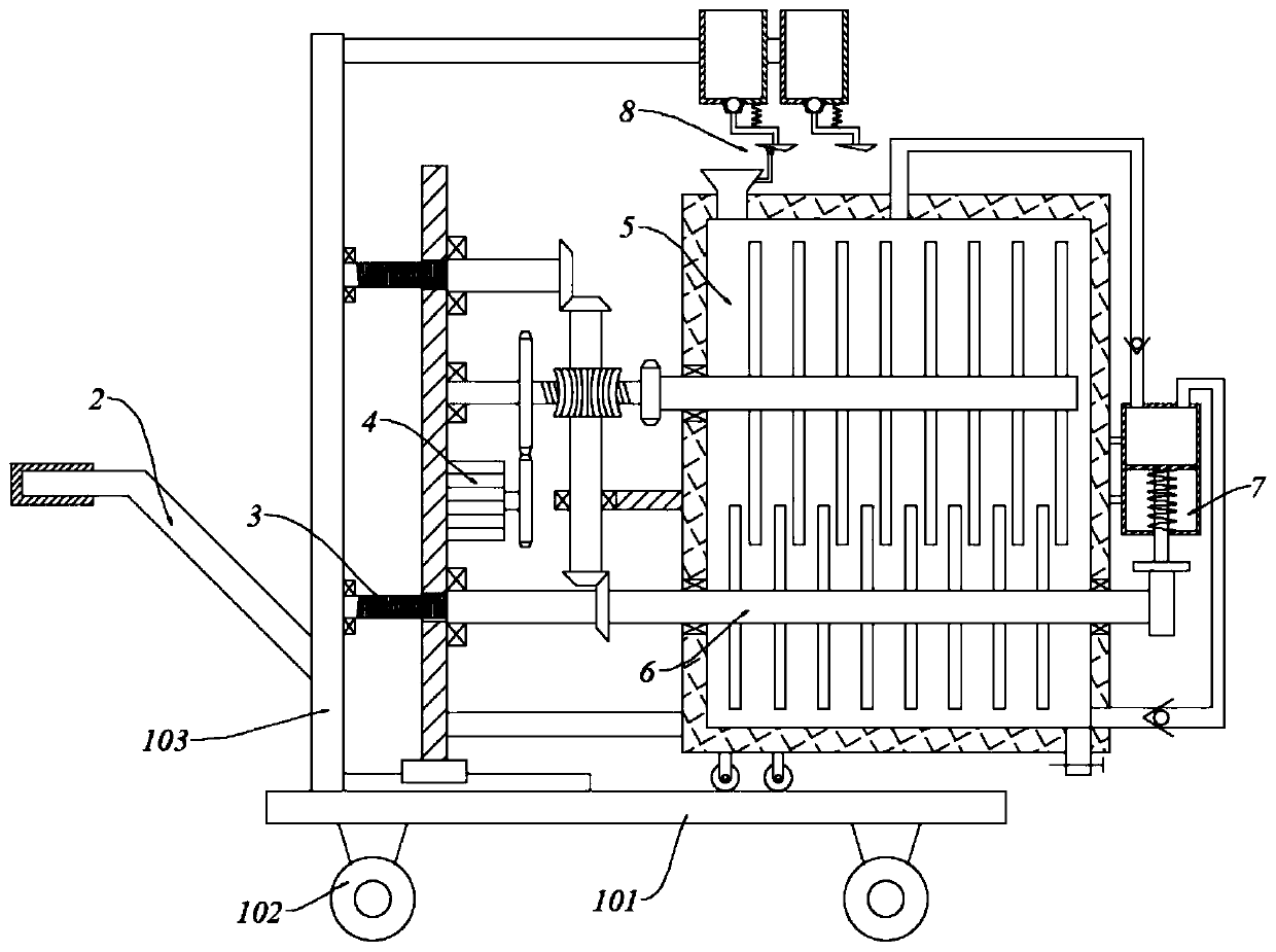
[0050] With reference to the accompanying drawings, a dissolving device for reciprocating shaking paint processing includes a car body, a drive assembly 4, a screw assembly 3, a dissolution tank 5, a stirring assembly 6, and a pumping assembly 7;
[0051] Car body comprises car plate 101, wheel 102 and stand plate 103, and car plate 101 bottom is equipped with wheel 102, and car plate 102 top left end is fixed with stand plate 103; Stand plate 103 right side is provided with screw assembly 3, and screw assembly 3 cooperates There is a drive assembly 4; the dissolution box 5 is arranged on the right side of the drive assembly 4, the dissolution box 5 is provided with a stirring assembly 6, and the right side of the dissolution box 5 is provided with a pumping assembly 7.
Embodiment 2
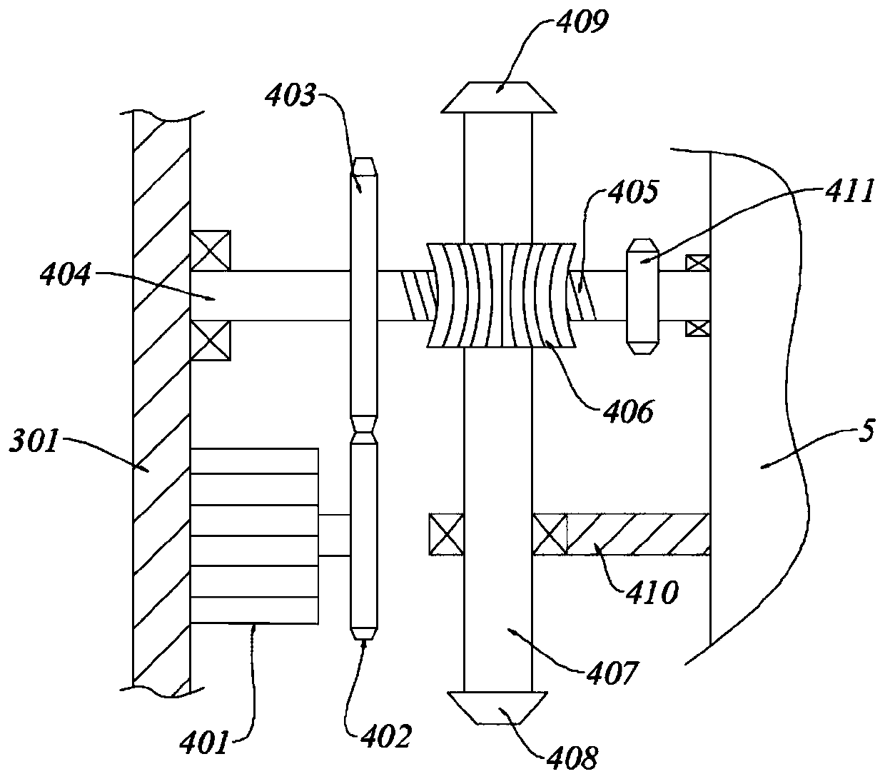
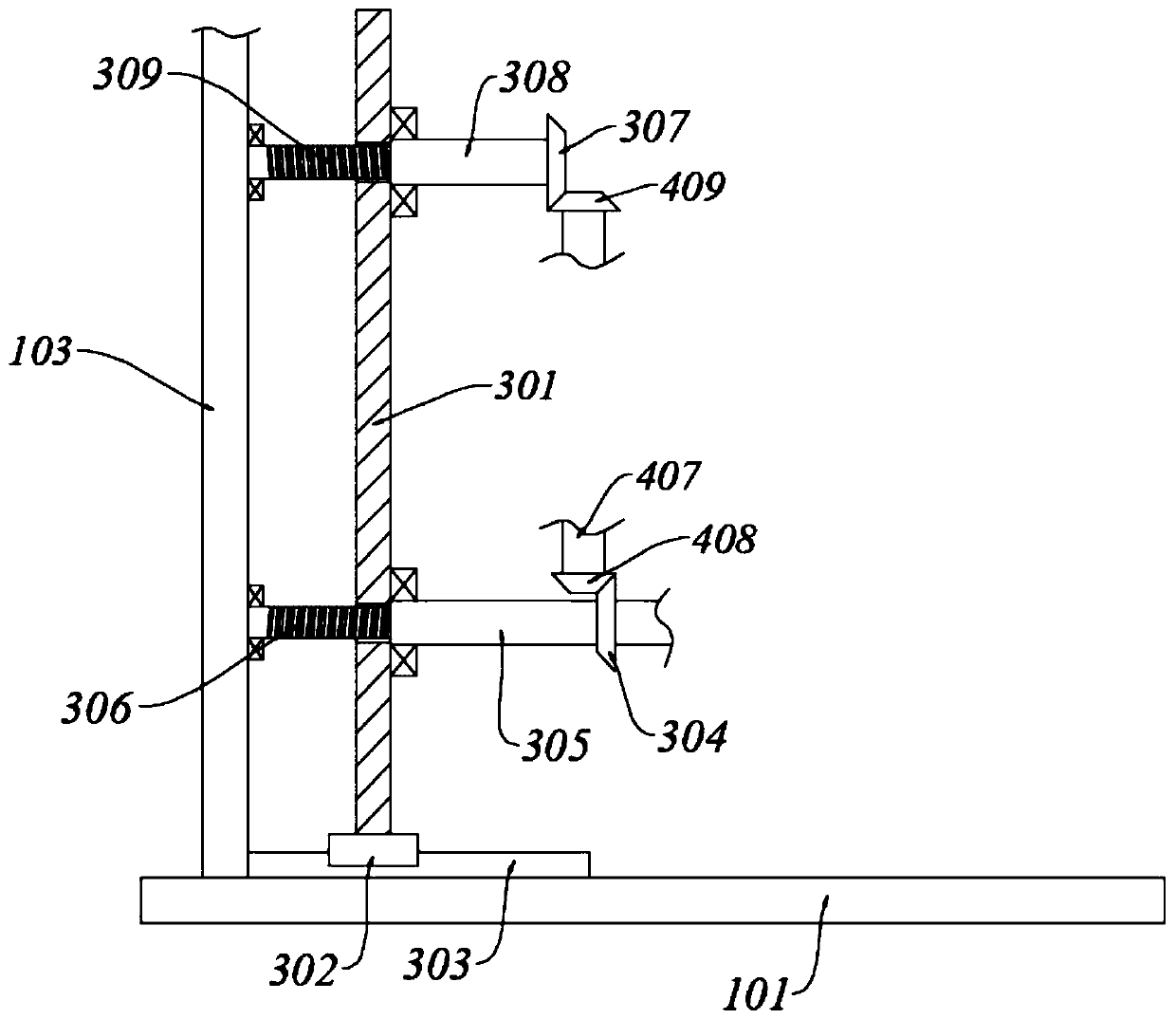
[0053] Reference attached Figure 1-5 , a reciprocating shaking type dissolution device for paint processing, comprising a car body, a drive assembly 4, a screw assembly 3, a dissolution tank 5, a stirring assembly 6, and a pumping assembly 7;
[0054] Car body comprises car plate 101, wheel 102 and stand plate 103, and car plate 101 bottom is equipped with wheel 102, and car plate 102 top left end is fixed with stand plate 103; Stand plate 103 right side is provided with screw assembly 3, and screw assembly 3 cooperates There is a drive assembly 4; the dissolution box 5 is arranged on the right side of the drive assembly 4, the dissolution box 5 is provided with a stirring assembly 6, and the right side of the dissolution box 5 is provided with a pumping assembly 7.
[0055] Wherein, the screw assembly 3 includes a moving plate 301, a slider 302, a slide rail 303, a No. 3 bevel gear 304, a No. 1 internally threaded tube 305, a No. 1 screw 306, a No. 4 bevel gear 307, a No. 2 ...
Embodiment 3
[0070] Wherein, the same or corresponding components as in Embodiment 1 and Embodiment 2 adopt the reference numerals corresponding to Embodiment 1 and Embodiment 2. For the sake of brevity, only the differences from Embodiment 2 are described below. The difference between this embodiment and embodiment two is:
[0071] The left side of the vertical plate 103 is also connected with a push-pull assembly 2, the push-pull assembly 2 includes a push-pull rod 201 and a plastic cover 202, the push-pull rod 201 is a bent rod, the right end is affixed to the vertical plate 103, and the left end is horizontally provided with a plastic cover 202.
[0072] It also includes a feed assembly 8; the feed assembly 8 includes a pole 801, a storage barrel 802, a conical cylinder 803, a plug 804, a lifting rod 805, a wedge block 806, a second type spring 807, a roller 808 and three No. connecting rod 809;
[0073] There is a pole 801 on the top of the vertical plate 103 to the right connecting ...
PUM
 Abstract
Description
Claims
Application Information
 - R&D
- Intellectual Property
- Life Sciences
- Materials
- Tech Scout
- Unparalleled Data Quality
- Higher Quality Content
- 60% Fewer Hallucinations
Browse by: Latest US Patents, China's latest patents, Technical Efficacy Thesaurus, Application Domain, Technology Topic, Popular Technical Reports.
© 2025 PatSnap. All rights reserved.Legal|Privacy policy|Modern Slavery Act Transparency Statement|Sitemap|About US| Contact US: help@patsnap.com


