
Driving device and driving method for speed-regulating and speed-reducing motor

A deceleration motor and driving device technology, which is applied in the deceleration device of AC motor, electric motor/converter plug, etc., can solve the problems of relay electric shock oxidation damage, long braking response time, high maintenance cost, etc., and achieve high braking efficiency Effect

Active Publication Date: 2021-06-22
东莞声索电子有限公司
View PDF5 Cites 0 Cited by
  • Summary
  • Abstract
  • Description
  • Claims
  • Application Information

AI Technical Summary

Problems solved by technology

[0002] Speed-adjusting and decelerating motor drives are generally controlled by analog, which cannot realize automatic intelligent control
[0003] Existing speed-regulating and decelerating motors use relay switching circuit or reverse drive to brake, and there will be a phenomenon of long braking response time (ie> 1 / 4 turn)
In addition, the relay is prone to ignition or high current, which will cause electric shock and oxidation damage, which will affect the service life. If it is to be used normally, it needs to be checked and replaced regularly, and its use and maintenance costs are high.
In addition, there will be reverse rotation and the brake response time is not constant

Method used


Image

  • Driving device and driving method for speed-regulating and speed-reducing motor
  • Driving device and driving method for speed-regulating and speed-reducing motor
  • Driving device and driving method for speed-regulating and speed-reducing motor

Examples


Embodiment Construction

[0054] In order to make the above objects, features and advantages of the present invention more comprehensible, specific implementations of the present invention will be described in detail below in conjunction with the accompanying drawings. In the following description, numerous specific details are set forth in order to provide a thorough understanding of the present invention. However, the present invention can be implemented in many other ways different from those described here, and those skilled in the art can make similar improvements without departing from the connotation of the present invention, so the present invention is not limited by the specific embodiments disclosed below.

[0055] In describing the present invention, it is to be understood that the terms "upper", "lower", "front", "rear", "left", "right", "vertical", "horizontal", "top", The orientation or positional relationship indicated by "bottom", "inner", "outer", etc. is based on the orientation or po...


PUM


Abstract

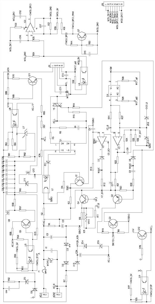
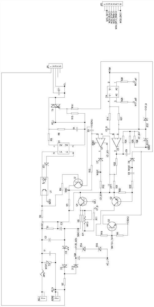
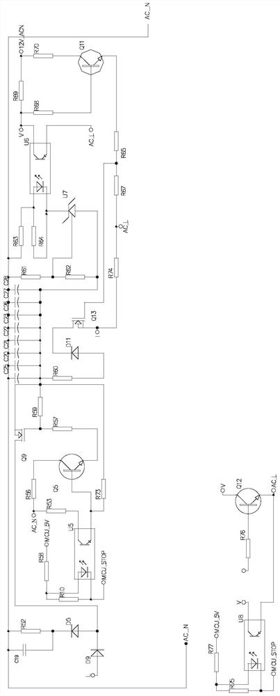
The invention discloses a speed regulation and reduction motor driving device and a driving method. The device comprises a motor coil; a motor start-stop control speed regulation circuit which is connected with the motor coil and is used for controlling the motor coil to start and stop; and a charging and discharging brake circuit which is connected with the motor coil and is used for providing direct current for the motor coil, so the motor coil is completely stopped. The speed regulation gear motor driving device is suitable for a speed regulation type gear motor with a speed ring, and motor starting can be achieved. In addition, a parking command of the single chip microcomputer can be responded in time through the charging and discharging brake circuit, the brake response of a motor coil is controlled within 1 / 16 circles, the brake efficiency is high, and the conditions of reverse rotation and unfixed brake response time are avoided.

Description

technical field [0001] The invention relates to the technical field of motor drive, in particular to a speed-regulating and decelerating motor driving device and a driving method implemented by the speed-regulating and decelerating motor driving device. Background technique [0002] Speed-adjusting and decelerating motor drives are generally controlled by analog, which cannot realize automatic intelligent control. [0003] Existing speed-regulating and decelerating motors use a relay switching circuit or a reverse drive to perform braking, and there will be a phenomenon of long braking response time (ie > 1 / 4 turn). In addition, the relay is prone to sparking or high current, resulting in electrocution and oxidation damage, thereby affecting the service life. Regular inspection and replacement are required for normal use, and the use and maintenance costs are high. In addition, reverse rotation occurs and the brake response time is not constant. Contents of the inventi...

Claims


Application Information

Patent Timeline
IPC IPC(8): H02P3/24
CPCH02P3/24
Inventor 秦小翔阎先锋
Owner 东莞声索电子有限公司
Learn More