Machining part automatic filter device

A technology for filtering devices and parts, applied in the field of automatic filtering devices for processing parts, can solve the problems of affecting filtering and separation, the offset and falling off of filter plates, and the burden on staff, and achieve the effects of avoiding filtering and separation, facilitating maintenance and replacement, and facilitating dismantling and installation.

Inactive Publication Date: 2019-11-12
嘉兴金芯研电子科技有限公司
View PDF8 Cites 2 Cited by
  • Summary
  • Abstract
  • Description
  • Claims
  • Application Information

AI Technical Summary

Problems solved by technology

[0003] According to a waste collection device for CNC machining centers disclosed in Patent No. CN201821681203.1, after the machining is completed, the nozzle sprays out the coolant to accelerate the cooling of the parts, and at the same time, wash away the slag attached to the workbench. Start the pump, and the pump will pump the mixture of coolant and slag to the separation device through the swarf conveying pipeline for separation. The separated slag enters other recycling processes. The separated coolant can be recycled, which is environmentally friendly and energy-saving. , in actual use, it still needs manpower to pour the separated coolant back to the cooling water tank every time, which increases the amount of labor and brings a great burden to the staff, and when manually pouring the water back into the water tank, it needs to The dismantling of the device seriously affected the efficiency of waste filtration and separation. At the same time, the filter plate lacked effective fixation, so that during the processing, the filter plate was easily affected by the vibration of the CNC machining center, causing it to shift and fall off, affecting normal operation. Filtration separation, for this purpose, we propose an automatic filtration device for processing parts

Method used


Image

  • Machining part automatic filter device
  • Machining part automatic filter device
  • Machining part automatic filter device

Examples


Embodiment Construction

[0023] The following will clearly and completely describe the technical solutions in the embodiments of the present invention with reference to the accompanying drawings in the embodiments of the present invention. Obviously, the described embodiments are only some, not all, embodiments of the present invention. Based on the embodiments of the present invention, all other embodiments obtained by persons of ordinary skill in the art without making creative efforts belong to the protection scope of the present invention.

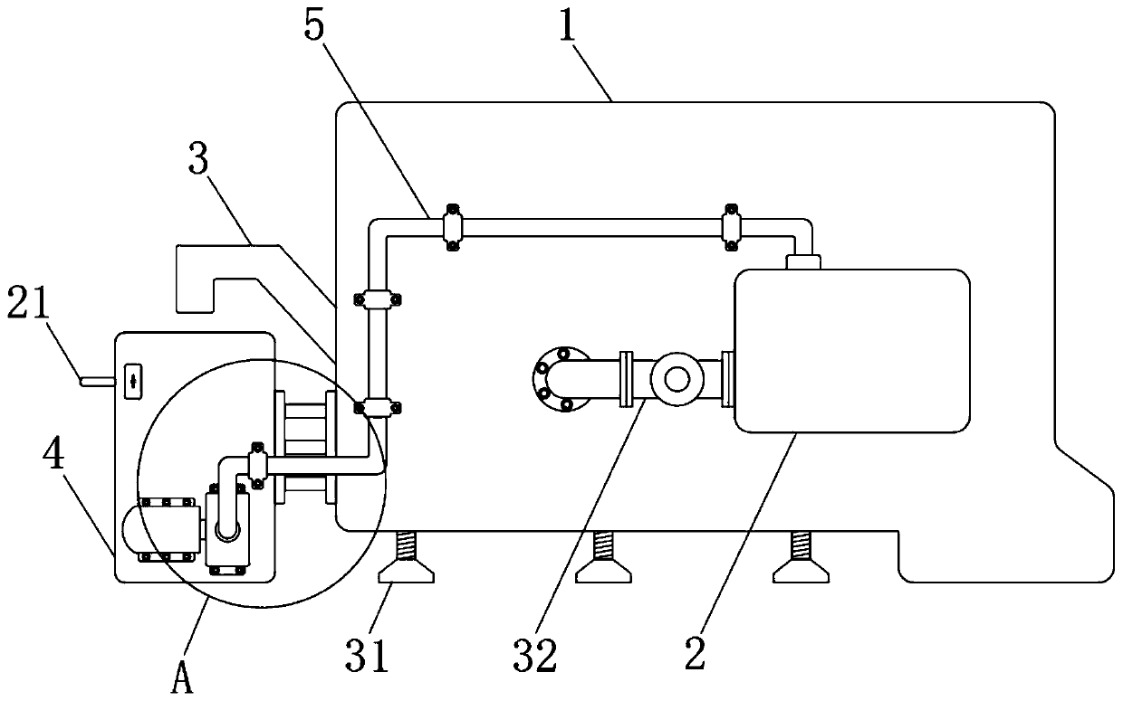
[0024] see Figure 1-6 , the present invention provides a technical solution: an automatic filtering device for processing parts, including a numerical control machining center 1, a plurality of adjustable legs 31 are fixedly fixed at the bottom of the numerical control machining center 1, and the numerical control machining center 1 is far away from the cabinet A water tank 2 is fixedly installed on one side of the door, and a conduction pipe 32 is fixedly in...


PUM


Abstract

The invention discloses a machining part automatic filter device. The machining part automatic filter device comprises a CNC machining center, wherein a plurality of adjustable support legs are fixedly installed at the bottom of the CNC machining center at equal intervals, a water tank is fixedly mounted on the side, away from a cabinet door, of the CNC machining center, and a conduction pipe is fixedly installed at a water outlet of the water tank; and the water tank fixedly communicates with the CNC machining center through the conduction pipe. The machining part automatic filter device is different from the prior art, and a filter element can be fixed effectively through arrangement of a clamping member, so that offset falling off, caused by vibration, of the filter element is avoided,and normal filtration separation is not affected; meanwhile, the filter element can be disassembled and installed conveniently while effective fixing of the filter element is ensured, and meanwhile, water circulation of a separated coolant can be performed automatically through arrangement of a water circulation component, so that the efficiency of filtration separation of sweeps is improved effectively; and no manpower is required, and great convenience is brought to the staff.

Description

technical field [0001] The invention relates to the technical field, in particular to an automatic filtering device for processing parts. Background technique [0002] The CNC machining center is a high-efficiency automatic machine tool suitable for processing complex parts composed of mechanical equipment and a CNC system. The parts are clamped in the workbench, and the CNC system automatically selects the tool according to the control process to cut the parts along the set processing route. During the finishing process, a large amount of heat will be released, which will increase the temperature of the part. [0003] According to a waste collection device for CNC machining centers disclosed in Patent No. CN201821681203.1, after the machining is completed, the nozzle sprays out the coolant to accelerate the cooling of the parts, and at the same time, wash away the slag attached to the workbench. Start the pump, and the pump will pump the mixture of coolant and slag to the ...

Claims


Application Information

Patent Timeline
Patent Type & Authority Applications(China)
IPC IPC(8): B01D29/05B01D29/96
CPCB01D29/05B01D29/96
Inventor 金波
Owner 嘉兴金芯研电子科技有限公司
Why Eureka
Try Eureka