
Anti-loosening and anti-vibration structure of hydraulic pipeline pipe clamp at vibration part in hydraulic system

A technology of vibration parts and hydraulic pipelines, which is applied in the direction of pipeline supports, pipes/pipe joints/fittings, mechanical equipment, etc., can solve the problems of hydraulic pipeline vibration intensification, hydraulic pipeline joint loosening, pipeline leakage, etc., to eliminate potential safety hazards, Ensure reliable fastening and avoid loose effect

Pending Publication Date: 2019-11-08
SHANGHAI BAOSTEEL IND TECHNOLOGICAL SERVICE
View PDF9 Cites 0 Cited by
  • Summary
  • Abstract
  • Description
  • Claims
  • Application Information

AI Technical Summary

Problems solved by technology

In some applications with large vibration, due to the large mechanical vibration in the workplace, after the hydraulic system has been in operation for a certain period of time, the inner circle of the pipe clamp will gradually become larger due to the impact of the vibration, so that the hydraulic pipe cannot be clamped and cannot be effectively achieved. The function of fastening the hydraulic pipeline will cause the vibration of the hydraulic pipeline to intensify, causing the hydraulic pipeline joint to loosen or the pipeline to leak, thus bringing certain safety hazards to the normal and reliable operation of the hydraulic system

Method used


Image

  • Anti-loosening and anti-vibration structure of hydraulic pipeline pipe clamp at vibration part in hydraulic system

Examples


Embodiment Construction

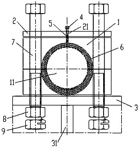
[0010] Example figure 1 As shown, the anti-loosening and anti-vibration structure of the hydraulic pipeline pipe clip in the hydraulic system of the present invention includes a pipe clip 1, an upper cover plate 2, a bottom plate 3, a compression bolt 4, a compression spring 5, some steel balls 6, two long Bolts 7 and two lock nuts 8, the pipe clip 1 is two semicircular hoops with a rectangular cross-section, the inner ring of the pipe clip 1 is provided with a circular long groove along the circumferential direction, and the upper cover plate 2 and the bottom plate 3 are respectively arranged on the top surface and the bottom surface of the pipe clamp 1, the two long bolts 7 penetrate into the upper cover plate 2, the tube clamp 1 and the bottom plate 2 sides in turn, and the two lock nuts 8 Screw in the bottom ends of the two long bolts 7 and fasten the upper cover plate 2, the pipe clamp 1 and the bottom plate 3, the middle part of the upper cover plate 2 has a screw hole 2...


PUM


Abstract

The invention discloses an anti-loosening and anti-vibration structure of a hydraulic pipeline pipe clamp at a vibration part in a hydraulic system. The pipe clamp in the structure is two semicircularhoops with rectangular cross sections, wherein a circular long groove is formed in an inner ring of the pipe clamp in the circumferential direction; an upper cover plate and a bottom plate are respectively arranged on the top surface and the bottom surface of the pipe clamp; two long bolts sequentially penetrate into the two sides of the upper cover plate, the pipe clamp and the bottom plate; twolocking nuts are screwed into the bottom ends of the two long bolts and the upper cover plate, the pipe clamp and the bottom plate are fastened by the two locking nuts; a screw hole which communicates with the circular long groove is formed in the middle of the upper cover plate; a plurality of steel balls are poured into the circular long groove through the screw hole; a compression spring is positioned in the screw hole, and the bottom end of the compression spring abuts against the steel balls in the circular long groove; and a compression bolt is screwed into the screw hole and the bottomend of the compression bolt abuts against the compression spring. The structure overcomes the defect of fixing a traditional hydraulic pipeline, ensures reliable fastening of the hydraulic pipeline,avoids loosening of pipeline joints or pipeline leakage, and avoids potential safety hazards in operation of the hydraulic system.

Description

technical field [0001] The invention relates to an anti-loosening and anti-vibration structure for a hydraulic pipeline pipe clamp at a vibrating part in a hydraulic system. Background technique [0002] The main function of the hydraulic system is to transmit power and motion, and it is widely used in the process control of industrial production. It usually consists of hydraulic components, hydraulic control components, hydraulic actuators and hydraulic accessories, among which hydraulic accessories include pipelines and accumulators. Pipes play a very important role in the hydraulic system, and generally the pipes are fixed with pipe clips. In some applications with large vibration, due to the large mechanical vibration in the workplace, after the hydraulic system has been in operation for a certain period of time, the inner circle of the pipe clamp will gradually become larger due to the impact of the vibration, so that the hydraulic pipe cannot be clamped and cannot be ...

Claims


Application Information

Patent Timeline
Patent Type & Authority Applications(China)
IPC IPC(8): F16L3/10F16L3/20
CPCF16L3/1091F16L3/20
Inventor 刘保国
Owner SHANGHAI BAOSTEEL IND TECHNOLOGICAL SERVICE
Learn More