Novel steel bar binding device
A new type of technology for steel bar binding, applied in the parts and packaging of binding machinery, can solve the problems of time-consuming, sore hands, complicated operation, etc., and achieve the effect of rapid cutting
- Summary
- Abstract
- Description
- Claims
- Application Information
AI Technical Summary
Problems solved by technology
Method used
Image

Examples
Embodiment 1
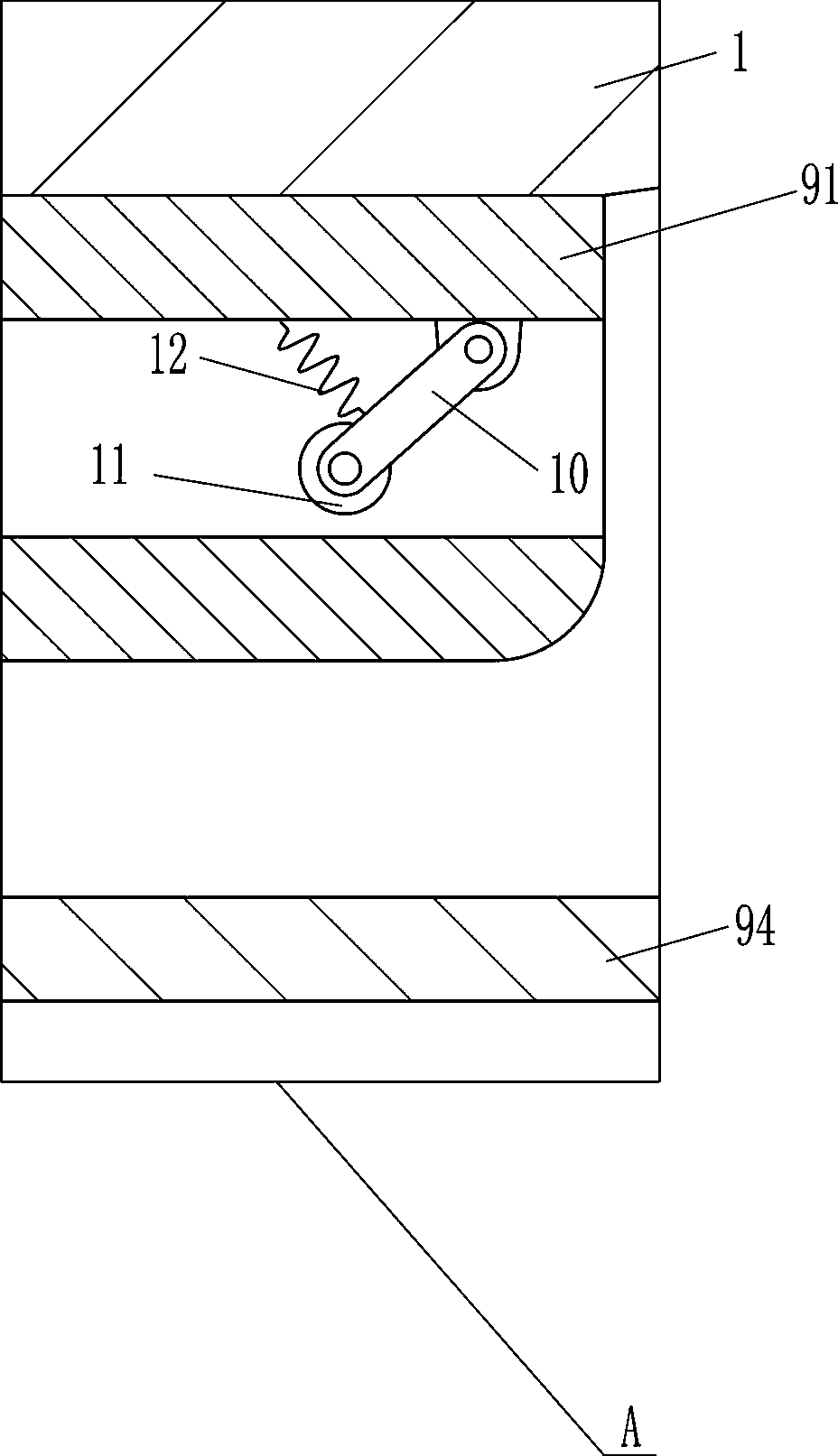
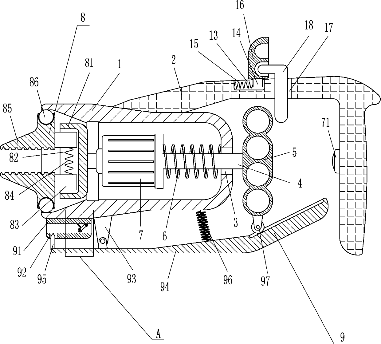
[0019] A new type of steel bar binding device, such as figure 1 As shown, it includes a cylindrical shell 1, a handle 2, a T-shaped slide bar 4, a handle 5, a first spring 6, a drive motor 7, a switch 71 and a clamping device 8, and a handle 2 is installed on the outer surface of the cylindrical shell 1. , the cylindrical shell 1 is connected with the handle 2 by means of bolt connection, the left side of the cylindrical shell 1 is open, the inner left side of the cylindrical shell 1 is a slope, and the right side of the cylindrical shell 1 has a sliding hole 3 for sliding The sliding type in the hole 3 is provided with a T-shaped slide bar 4, and the right end of the T-shaped slide bar 4 is equipped with a handle 5, and the handle 5 is located on the right side of the cylindrical shell 1, between the T-shaped slide bar 4 and the inner right side of the cylindrical shell 1 A first spring 6 is connected, and a drive motor 7 is installed on the left side of the T-shaped slide ba...
Embodiment 2
[0024] A new type of steel bar binding device, such as Figure 1-2 As shown, it includes a cylindrical shell 1, a handle 2, a T-shaped slide bar 4, a handle 5, a first spring 6, a drive motor 7, a switch 71 and a clamping device 8, and a handle 2 is installed on the outer surface of the cylindrical shell 1. , the left side of the cylindrical shell 1 is an open type setting, the left side of the cylindrical shell 1 is a slope, the right side of the cylindrical shell 1 has a sliding hole 3, and the sliding type in the sliding hole 3 is provided with a T-shaped slide bar 4, T The right end of the type slide bar 4 is equipped with a handle 5, and the handle 5 is located on the right side of the cylindrical shell 1, and the first spring 6 is connected between the T-shaped slide bar 4 and the inner right side of the cylindrical shell 1, and the left side of the T-shaped slide bar 4 A drive motor 7 is installed, and the drive motor 7 is located in the cylindrical shell 1. A switch 71...
Embodiment 3
[0031] A new type of steel bar binding device, such as Figure 1-2 As shown, it includes a cylindrical shell 1, a handle 2, a T-shaped slide bar 4, a handle 5, a first spring 6, a drive motor 7, a switch 71 and a clamping device 8, and a handle 2 is installed on the outer surface of the cylindrical shell 1. , the left side of the cylindrical shell 1 is an open type setting, the left side of the cylindrical shell 1 is a slope, the right side of the cylindrical shell 1 has a sliding hole 3, and the sliding type in the sliding hole 3 is provided with a T-shaped slide bar 4, T The right end of the type slide bar 4 is equipped with a handle 5, and the handle 5 is located on the right side of the cylindrical shell 1, and the first spring 6 is connected between the T-shaped slide bar 4 and the inner right side of the cylindrical shell 1, and the left side of the T-shaped slide bar 4 A drive motor 7 is installed, and the drive motor 7 is located in the cylindrical shell 1. A switch 71...
PUM
 Abstract
Description
Claims
Application Information
 - R&D
- Intellectual Property
- Life Sciences
- Materials
- Tech Scout
- Unparalleled Data Quality
- Higher Quality Content
- 60% Fewer Hallucinations
Browse by: Latest US Patents, China's latest patents, Technical Efficacy Thesaurus, Application Domain, Technology Topic, Popular Technical Reports.
© 2025 PatSnap. All rights reserved.Legal|Privacy policy|Modern Slavery Act Transparency Statement|Sitemap|About US| Contact US: help@patsnap.com