
Full-speed-range composite strategy control method for permanent magnet synchronous motor

A technology of permanent magnet synchronous motor and strategic control, which is applied in motor control, motor generator control, AC motor control, etc., and can solve problems such as complex algorithms, chattering problems, and discontinuous switch control

Inactive Publication Date: 2019-11-05
NANJING UNIV OF SCI & TECH
View PDF8 Cites 19 Cited by
  • Summary
  • Abstract
  • Description
  • Claims
  • Application Information

AI Technical Summary

Problems solved by technology

The common methods based on the fundamental frequency model are as follows: the extended Kalman filter algorithm can effectively reduce the influence of the system and measurement on the state estimation, but the algorithm is relatively complex and has a considerable amount of calculation; the model refers to the adaptive system It has the characteristics of fast dynamic response and high robustness, but it is greatly affected by the change of motor parameters, and the calculation requirements are high; the algorithm of the sliding mode observer method is simple, easy to implement in engineering, and can solve complex industrial control problems well, but Due to its discontinuous switch control in nature, chattering problems are inevitable, especially at low speeds, and some measures to suppress chattering are required in practical applications

Method used


Image

  • Full-speed-range composite strategy control method for permanent magnet synchronous motor
  • Full-speed-range composite strategy control method for permanent magnet synchronous motor
  • Full-speed-range composite strategy control method for permanent magnet synchronous motor

Examples


Embodiment

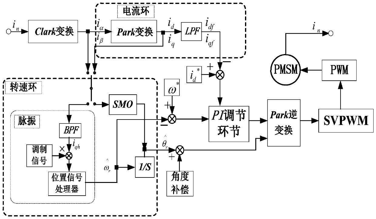
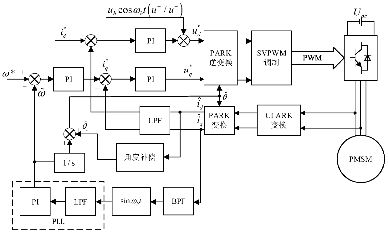
[0111] Such as figure 1 As shown, it is the overall principle block diagram of the control method of the present invention. The method provides a compound strategy control method for the full speed range of the permanent magnet synchronous motor, including the pulse vibration high-frequency signal injection method in the zero-low speed section, and the sliding mode observer in the medium-high speed section. Among them, the pulse vibration high-frequency signal injection method obtains the rotor position information based on the inherent saliency of the motor or the saturation characteristics of the magnetic circuit, the sliding mode observer obtains the rotor position information based on the back EMF of the motor, and the weighted average method;

[0112] A full speed range compound strategy control method of a permanent magnet synchronous motor of the present invention comprises the following steps:

[0113] Step 1: The collected phase currents in the two-phase windings of ...


PUM


Abstract

The invention discloses a full-speed-range composite strategy control method for a permanent magnet synchronous motor. The method comprises the following steps: respectively carrying out Clark transformation and Park transformation on an acquired phase current of the permanent magnet synchronous motor to obtain a synchronous rotation d-q coordinate system current value; injecting a high-frequencysignal into the direct axis of an estimated rotating coordinate system in a zero-low speed stage, and processing the converted phase current through an LPF and a BPF respectively; obtaining a fundamental component of the current signal through the LPF, and obtaining a high-frequency component of the current signal through the BPF; multiplying the high-frequency response by a sinusoidal modulationsignal, sending the multiplied high-frequency response to a position signal processor to obtain estimated feedback values of a rotating speed loop and a current loop, and generating a PWM signal through PI adjustment, Park inverse transformation and an SVPWM module, thereby realizing real-time control of the permanent magnet synchronous motor. According to the invention, no extra position sensor needs to be added, the control is accurate, the response speed is high, the robustness of the system is enhanced, and the control performance of the system is improved.

Description

technical field [0001] The invention relates to the field of electric drive and motor control, in particular to a full speed range composite strategy control method for a permanent magnet synchronous motor. Background technique [0002] With the increasing level of industrialization and the continuous development of electric drive technology, motor drive control has ushered in new development opportunities and challenges. In addition to requiring high power density and high efficiency, it also needs to have high output performance and high reliability. This has become the crux of motor drive control. The permanent magnet synchronous motor (Permanent Magnet Synchronous Motor, PMSM) has the advantages of both structure and performance. It is not only small in size and simple in structure, but also has the characteristics of high power density and high efficiency, and has broad application prospects. The PMSM drive system relies on accurate rotor position feedback information....

Claims


Application Information

Patent Timeline
IPC IPC(8): H02P6/182H02P21/14H02P25/026H02P27/08
CPCH02P6/182H02P21/14H02P25/026H02P27/08H02P2203/03H02P2207/05
Inventor 屠逸翔胡雅倩王绍帅
Owner NANJING UNIV OF SCI & TECH
Learn More