A suction and discharge structure for a compressor

A technology of suction and exhaust, compressor, applied in the field of compressors, can solve the problems of reducing the exhaust efficiency of the compressor, reducing the suction efficiency of the compressor, collision between the movement and the casing, etc. Gas efficiency, the effect of improving gas transmission efficiency

Active Publication Date: 2020-10-09
CHANGHONG HUAYI COMPRESSOR CO LTD
View PDF7 Cites 0 Cited by
  • Summary
  • Abstract
  • Description
  • Claims
  • Application Information

AI Technical Summary

Problems solved by technology

[0002] In the current suction and exhaust structure of refrigerator compressors, the suction muffler has only one air outlet, and the air outlet of the muffler is pressed against the air inlet of the valve plate by buckles, so that an airtight structure is formed between the air outlet of the muffler and the valve plate , the gaseous refrigerant coming out of the muffler is directly sucked into the cylinder. There are two defects in this structure. One is that during the transportation of the compressor, the core and the shell will collide. In addition, during the operation of the compressor, especially when the compressor starts And at the moment of shutdown, the compressor vibrates greatly, and the buckle that fixes the outlet of the muffler is easy to loosen, resulting in the tight seal between the outlet of the muffler and the valve plate, resulting in the failure of the suction muffler, which cannot eliminate noise and reduce suction. The pulsation effect will also reduce the suction efficiency of the compressor and reduce the cooling capacity of the compressor. In addition, the lubricating oil mist mixed in the gaseous refrigerant will be directly sucked into the cylinder without passing through the muffler, and finally discharged into the compressor through the exhaust channel. to the refrigeration system, reducing the heat transfer efficiency of the refrigeration system and increasing the power consumption of the refrigeration system
[0003] In addition, in the suction and exhaust structure of the current refrigerator compressor, the cylinder head, cylinder head gasket, valve plate assembly, suction valve plate, and valve plate gasket are fixed and pressed on the crankcase in sequence by screws. , Suction valve plate, valve plate gasket, and crankcase end faces are all flatly bonded to each other, affected by the processing technology of the parts, in the case of poor flatness, the exhaust gas will not be tightly bonded to each other Refrigerant gas leakage is easily generated during the process, which reduces the exhaust efficiency of the compressor and reduces the cooling capacity of the compressor.

Method used


Image

  • A suction and discharge structure for a compressor
  • A suction and discharge structure for a compressor
  • A suction and discharge structure for a compressor

Examples


Embodiment Construction

[0065] Attached below Figure 1-30 The present invention is described in further detail with specific embodiment:

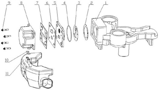
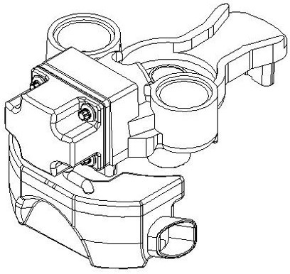
[0066] A suction and exhaust structure for a compressor, including a crankcase 1, a valve plate sealing gasket 2, a suction valve plate 3, a valve plate sealing ring 4, a valve plate 5, an exhaust valve plate 6, and a cylinder head gasket Sheet 7, cylinder head 8, mounting screw 9, muffler sealing ring 10, suction muffler 11,

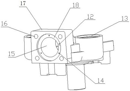
[0067] The crankcase 1 includes a cylinder block 17 and an exhaust buffer cavity 13, the exhaust buffer cavity 13 is cast on the right side of the cylinder block 17, and the center of the end face of the cylinder block 17 is milled with a stepped hole 18, and the stepped hole The inside of 18 is drilled with cylinder hole 15, and the step surface of step hole 18 is drilled with valve plate positioning hole 14 and exhaust hole 12, and is drilled with threaded hole 16 on the four angles of described cylinder block 17 end faces, and describe...


PUM


Abstract

The invention discloses a gas suction and discharge structure for a compressor. The gas suction and discharge structure comprises a crankcase (1), a valve plate seal gasket (2), a gas suction valve disc (3), a valve plate (5), a gas discharge valve disc (6), a cylinder cover seal gasket (7), a cylinder cover (8), a mounting screw (9) and a gas suction silencer (11). The end face of a cylinder body(17) of the crankcase (1) is provided with a step hole (18), a valve plate locating hole (14) and a first exhaust outlet (12). The rear end face of the valve plate (5) is provided with a round boss (57), a locating column (52) and a fifth exhaust outlet (51). An exhaust cavity (81) and a gas suction cavity (83) are formed in the cylinder cover (8). A gas discharge valve disc limiting column (84)is arranged in the exhaust cavity (81). The bottom face of the gas suction cavity (83) is provided with an oil leakage hole (85) and two gas inlet pipes connected with a gas outlet pipe of the gas suction silencer (11). Through the gas suction and discharge structure, gas leakage can be reduced, gas transfer efficiency of the compressor is promoted, gas suction noise of the compressor is lowered,and the gas suction and discharge structure has wide market prospects.

Description

technical field [0001] The invention relates to the technical field of compressors, in particular to a suction and discharge structure for a compressor. Background technique [0002] In the current suction and exhaust structure of refrigerator compressors, the suction muffler has only one air outlet, and the air outlet of the muffler is pressed against the air inlet of the valve plate by buckles, so that an airtight structure is formed between the air outlet of the muffler and the valve plate , the gaseous refrigerant coming out of the muffler is directly sucked into the cylinder. There are two defects in this structure. One is that during the transportation of the compressor, the core and the shell will collide. In addition, during the operation of the compressor, especially when the compressor starts And at the moment of shutdown, the compressor vibrates greatly, and the buckle that fixes the outlet of the muffler is easy to loosen, resulting in the tight seal between the ...

Claims


Application Information

Patent Timeline
Patent Type & Authority Patents(China)
IPC IPC(8): F04B39/12F04B39/10F04B39/04F04B39/00
CPCF04B39/00F04B39/0083F04B39/04F04B39/10F04B39/122F04B39/125F04B39/128
Inventor 卢俊陈汉章陈永安戢金国白玉芳谌强何四发
Owner CHANGHONG HUAYI COMPRESSOR CO LTD
Why Eureka
Try Eureka