Cloth drying device for a rotary screen printing machine

A cloth drying and rotary screen printing technology, which is applied to screen printing machines, general parts of printing machinery, printing machines, etc., can solve the problems of fabric surface temperature field disorder, large space occupation, and low utilization rate, and achieve guaranteed Drying effect, reduced ventilation area, good drying effect

Active Publication Date: 2021-03-16
台州智子科技有限公司
View PDF11 Cites 0 Cited by
  • Summary
  • Abstract
  • Description
  • Claims
  • Application Information

AI Technical Summary

Problems solved by technology

Temperature control is the most important for the drying function of the drying room. The temperature should not be too high or too low. If it is too high, it will easily brighten the color of the printing and dyeing, while the low temperature may not completely solidify the color paste.
[0003] The drying device of the existing rotary screen printing machine is to place the fabric flat, provide a heat source in the drying room and use a fan to diffuse the hot air to various positions in the room. This device ignores the air circulation model of the fabric drying environment. The temperature field on the surface of the fabric is disturbed, and the drying degree of the color paste is not good
At the same time, the printing speed of the rotary screen printing machine is 1.5-3 times faster than that of the flat screen printing machine, so the drying room must be lengthened to ensure that the fabric has enough time to dry, but the drying room is too long to take up a lot of space and the utilization rate is not high. it is necessary to improve

Method used


Image

  • Cloth drying device for a rotary screen printing machine
  • Cloth drying device for a rotary screen printing machine
  • Cloth drying device for a rotary screen printing machine

Examples


Embodiment Construction

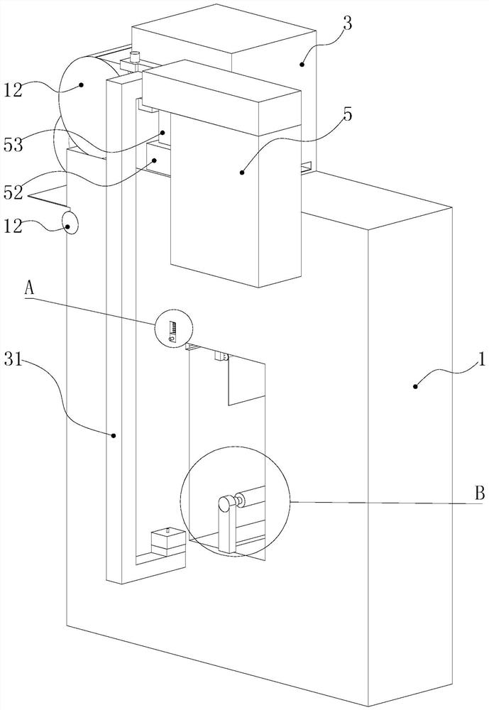
[0021] Such as Figure 1-7 As shown, a cloth drying device of a rotary screen printing machine includes an oven 1, a feeding mechanism, a drying mechanism, a hot air recovery mechanism and a collecting mechanism, and the material collecting mechanism includes a feeding port 11 and a feeding roller 12, The feed inlet 11 is provided on the side wall top of the oven 1, and the feed roller 12 is a conventional round roller, which is arranged in the feed inlet, and the two ends are respectively connected to the inner wall of the oven by rotation. The cloth can be flattened into the oven for drying.

[0022] Described drying mechanism comprises guide roller 2, hot air blower 21, air inlet 22, air inlet pipe 23, heating plate 28 and air guide member, and described hot air blower 21 selects conventional hot air blower for use, is fixed on the oven top, and described air inlet The tuyere 22 is opened on the side wall of the oven, positioned at the top of the feed inlet. The air inlet ...


PUM


Abstract

The invention discloses a cloth drying device of a circular screen printing machine. The device comprises a feeding mechanism, a drying mechanism, a hot air recovery mechanism and a collecting mechanism, wherein the drying mechanism comprises a drying oven, a plurality of guide rollers and a blowing assembly, the guide rollers and the blowing assembly are arranged in the drying oven, and the guiderollers are distributed on the inner wall of the drying oven in a vortex shape. Through the guide rollers which are arranged in the drying oven in the vortex shape, cloth can be spirally wound in thedrying oven, the effective space in the drying oven is fully utilized, and the occupied space of the drying oven is saved. The guide rollers are distributed in the vortex shape, and it can be ensuredthat each guide roller is only in contact with the bottom surface of the cloth, so that the printing surface is prevented from being in contact with the guide rollers, and a printed pattern is prevented from being damaged.

Description

technical field [0001] The invention belongs to the technical field of textile machinery, in particular to a cloth drying device of a rotary screen printing machine. Background technique [0002] The drying room is the drying equipment of the rotary screen printing machine. After the fabric is printed and dyed by the rotary screen, the color paste on the fabric is still in a liquid or partially liquid-solid mixed state. The final product requires the color paste to be embedded in the surface of the fabric in a solid state. This requires the drying room to quickly solidify the color paste by means of high temperature and high pressure. Temperature control is the most important for the drying function of the drying room. The temperature should not be too high or too low. If it is too high, it will easily brighten the color of the printing and dyeing, while the low temperature may not completely solidify the color paste. [0003] The drying device of the existing rotary screen...

Claims


Application Information

Patent Timeline
Patent Type & Authority Patents(China)
IPC IPC(8): B41F23/04B41F15/12
CPCB41F15/12B41F23/0426B41P2215/10
Inventor 郑锦锦
Owner 台州智子科技有限公司
Why Eureka
Try Eureka