
Mortar anti reload device

A mortar and anti-heavy technology, which is applied in the field of mortar anti-heavy equipment, can solve the problems of psychological will damage, impact on launch, secondary reloading, etc., and achieve improved safety, convenient use, and high reliability. Effect

Active Publication Date: 2019-11-01
中联天通科技(北京)有限公司
View PDF2 Cites 3 Cited by
  • Summary
  • Abstract
  • Description
  • Claims
  • Application Information

AI Technical Summary

Problems solved by technology

A large number of equipment and wide application of mortars make the launch safety of mortars and ammunition particularly important and prominent; but improper storage environment will make mortar ammunition have a higher probability of blind fire or delayed fire At that time, due to the flames on the battlefield and the sound of explosions one after another, the gunner was difficult to distinguish the firing sound under the condition of fatigue and tension, and mechanically carried out rapid reloading, before the first loaded mortar flew out of the muzzle. Loading the second round of mortar will cause the phenomenon of secondary reloading (reloading)
After the reloading phenomenon occurs, it will affect the launch and delay the fighter plane, and it may cause the ammunition to explode or explode early, resulting in the destruction of the artillery, causing heavy loss of life and property and great damage to the psychological will of the troops.
In order to prevent such accidents, the existing anti-reloading devices mainly include photoelectric and electromagnetic; Insufficiency such as large influence of human factors has not been well popularized and applied. Therefore, in order to solve the above problems, it is urgent to design an anti-reloading device with practical promotion value to eliminate possible chamber explosion, muzzle explosion or early explosion. Potential hidden dangers such as safety accidents, further improving the safety of mortar firing

Method used


Image

  • Mortar anti reload device
  • Mortar anti reload device
  • Mortar anti reload device

Examples


Embodiment Construction

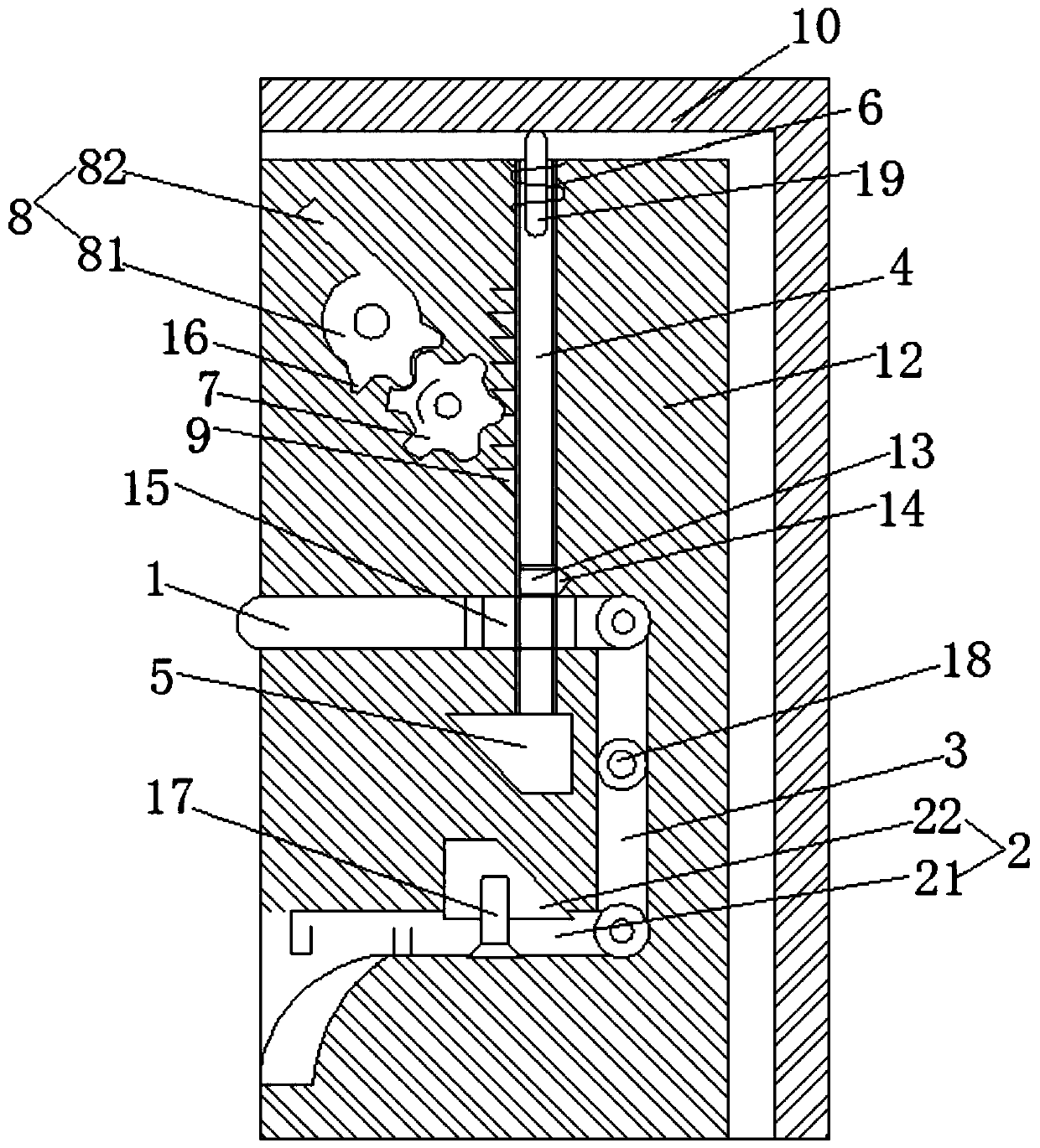
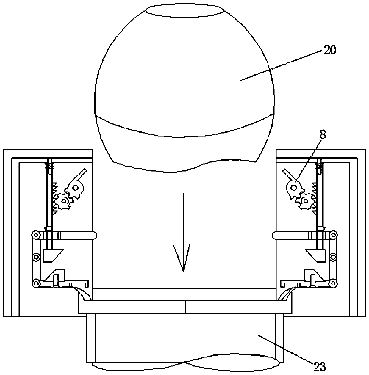
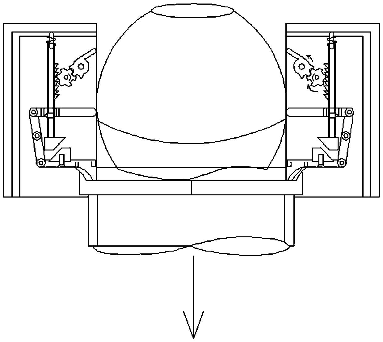
[0023] Such as figure 1 The mortar anti-reloading device shown includes a main body; the main body is tightly hooped to the mortar muzzle by a base; the main body is composed of two anti-reloading mechanisms installed symmetrically on the outside of the mortar bore; the The anti-reinstallation mechanism includes a body 12, a body assembly installed on the body 12, a connection system and a bullet-stopping assembly; the top of the body 12 is covered with a cover plate 10; the body assembly is connected to the bullet-stopping assembly through a connection system;

[0024] The body assembly includes a first slider 1, a second slider 2 and a rocker 3; the first slider 1 is connected to the second slider 2 through the rocker 3; the first slider 1 and the second The sliders 2 are respectively movably installed in the first chute and the second chute opened on both sides of the body 12, and the first slider 1 is located above the second slider 2;

[0025] The connecting system inclu...


PUM


Abstract

The invention discloses a mortar anti reload device. The mortar anti reload device comprises a main body, wherein the main body is tightly hooped to a mortar muzzle through a base; the main body is composed of two anti reload mechanisms symmetrically installed outside a mortar bore; and each anti reload mechanism comprises a body, a body component, a connecting system and a bullet retaining component installed on the body, wherein a cover plate is covered on the upper portion of the body, and the body component is connected with the bullet retaining component through the connecting system. Themortar anti reload device cannot increase the tactical actions, affect the actual firing speed and change a trajectory of a mortar shell; the device is suitable for various types of mortars, has goodadaptability with weapons and ammunition, is convenient to use, and has high reliability and practical promotion value; and the reloading of the shell is prevented or avoided before the first loadedmortar shell flies out of the muzzle due to blind fire or delayed fire and the like, so that the potential hidden dangers of safety accidents, such as bore explosion, muzzle explosion or early explosion, are eliminated, and the safety is improved during firing the shell.

Description

technical field [0001] The invention relates to a mortar anti-reloading device, which belongs to the technical field of mortar loading and launching. Background technique [0002] As one of the main combat equipment for the army, marine corps, and airborne troops to carry out fire strikes and support tasks, mortars have been used in previous wars due to their small size, light weight, curved trajectory, high power, and easy use and portability. Both have played an extremely important role. In modern warfare, mortars are still an indispensable firepower system for ground combat, especially in mountainous, jungle, water network, and urban areas. A large number of equipment and wide application of mortars make the launch safety of mortars and ammunition particularly important and prominent; but improper storage environment will make mortar ammunition have a higher probability of blind fire or delayed fire At that time, due to the flames on the battlefield and the sound of expl...

Claims


Application Information

Patent Timeline
Patent Type & Authority Applications(China)
IPC IPC(8): F41A17/14
CPCF41A17/14
Inventor 丁向赵磊仲伟君刘秋生周祥
Owner 中联天通科技(北京)有限公司
Learn More