
A cutting device for knitted fabric processing

A knitted fabric and cutting technology, which is applied in the cutting of textile materials, metal processing, textiles and papermaking, etc., can solve the problems of unstable fixation of fabrics, poor cutting quality, and high labor intensity, and achieves good fixation effect. The effect of improving cutting quality and increasing service life

Active Publication Date: 2021-08-06
LANGSHA KNITTING
View PDF0 Cites 0 Cited by
  • Summary
  • Abstract
  • Description
  • Claims
  • Application Information

AI Technical Summary

Problems solved by technology

[0003] In the process of knitted fabric processing, the fabric will be trimmed, cut, slitting and other cutting operations according to the requirements. The traditional cutting operations are mostly manual operations. When cutting manually, because the fabric is not fixed stably, not only the work efficiency Low, labor-intensive, and poor cutting quality, therefore, in view of the above status quo, it is urgent to develop a cutting device for knitted fabric processing to overcome the shortcomings in current practical applications

Method used


Image

  • A cutting device for knitted fabric processing
  • A cutting device for knitted fabric processing
  • A cutting device for knitted fabric processing

Examples


Embodiment 1

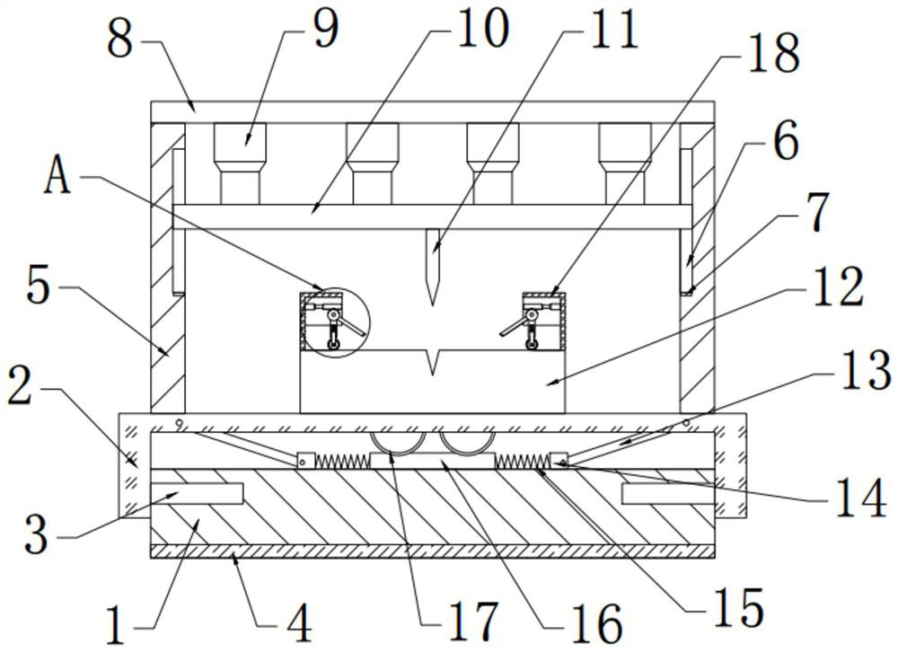
[0026] see Figure 1~3 , in an embodiment of the present invention, a cutting device for knitted fabric processing, including a base 1, the top of the base 1 is slidably connected with a mounting plate 2, and a shock absorbing mechanism is provided between the mounting plate 2 and the base 1, The top of the mounting plate 2 is fixedly connected with a placement table 12, the left and right sides of the placement table 12 are provided with a support plate 5 fixedly connected with the installation plate 2, and the top of the support plate 5 is fixedly connected with a top plate 8. The lower side of the top plate 8 is provided with a pressing plate 10, the first telescopic rod 9 is fixedly connected between the pressing plate 10 and the top plate 8, the bottom of the pressing plate 10 is fixedly connected with a blade 11, and the top left and right sides of the placing table 12 are arranged There is a fixed mechanism.

Embodiment 2

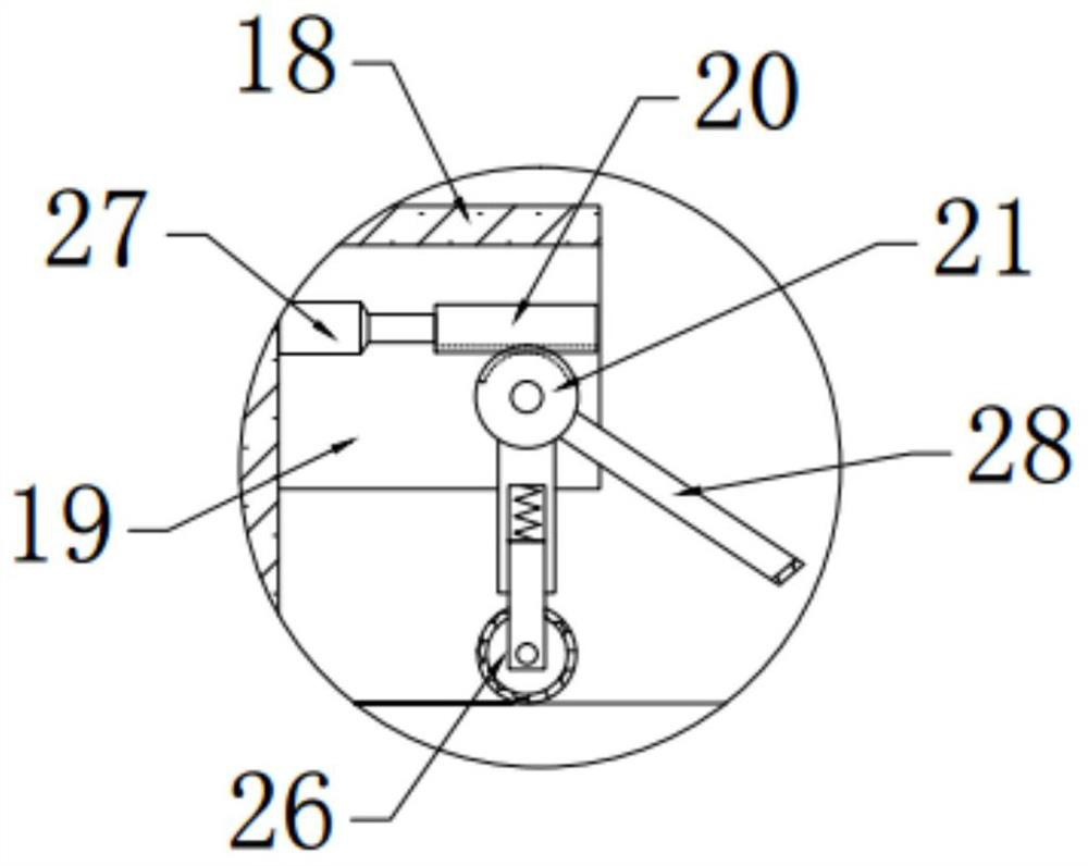
[0028] In this embodiment, the fixing mechanism includes a fixing plate 18, a baffle plate 19, a pulley 26, and a pressing block 28. The fixing plate 18 is fixedly connected and arranged on the top of the left and right ends of the placing table 12, and the front and rear sides of the fixing plate 18 are Both baffles 19 are fixedly connected, and a rotating rod 22 is hinged between the baffles 19 on both sides. Two gears 21 are fixedly connected on the rotating rod 22, and a rack 20 is provided on the top of the gear 21 for meshing connection. The second telescopic rod 27 is fixedly connected between the rack 20 and the fixed plate 18, the bottom of the gear 21 is fixedly connected with a connecting block 23, and the lower side of the connecting block 23 is slidably connected with a movable block 24, The movable block 24 and the connecting block 23 are fixedly connected with a spring, and the left side of the movable block 24 is bolt-connected with a motor 25, and the output en...


PUM


Abstract

The invention relates to the technical field of knitted fabric processing, in particular to a cutting device for knitted fabric processing. , the left and right sides of the placing table are provided with supporting plates, the top of the supporting plate is provided with a top plate, the lower side of the top plate is provided with a pressing plate, the first telescopic rod is arranged between the pressing plate and the top plate, the bottom of the pressing plate is fixedly connected with a blade, and the left and right sides of the top of the placing table are arranged. The side is provided with a fixing mechanism. In the present invention, by setting the fixing mechanism, the fabric on the placing table can be flattened to make the fabric smooth, and the fabric can be fixed on the placing table through a pressing block. By setting a shock absorbing mechanism, the impact of vibration on the blade can be reduced. The impact of cutting is beneficial to improve the cutting quality. By setting the chute, the stability of the pressure plate moving up and down can be ensured. By setting the pressure sensor, the cutting depth of the blade can be effectively controlled.

Description

technical field [0001] The invention relates to the technical field of knitted fabric processing, in particular to a cutting device for knitted fabric processing. Background technique [0002] Knitted fabrics are fabrics formed by bending yarns into loops with knitting needles and interlocking them. The difference between knitted fabrics and woven fabrics lies in the shape of the yarns in the fabric. Knitting is divided into weft knitting and warp knitting. At present, knitted fabrics are widely used in clothing fabrics and linings, home textiles and other products, and are loved by consumers. [0003] In the process of knitted fabric processing, the fabric will be trimmed, cut, slitting and other cutting operations according to the requirements. The traditional cutting operations are mostly manual operations. When cutting manually, because the fabric is not fixed stably, not only the work efficiency Low, labor-intensive, and poor cutting quality, therefore, in view of the ...

Claims


Application Information

Patent Timeline
Patent Type & Authority Patents(China)
IPC IPC(8): B26D1/08B26D7/02B26D7/08B26D7/00D06H7/00
CPCB26D1/085B26D7/00B26D7/015B26D7/025B26D7/08D06H7/00
Inventor 翁荣金刘爱莲张体健
Owner LANGSHA KNITTING
Learn More