
U.2 interface multi-hard-disk management backboard and method

A technology with multiple hard disks and interfaces, applied in the fields of electrical digital data processing, special data processing applications, climate sustainability, etc., can solve the problems of irrecoverable damage of hard disks, adverse effects of NVME hard disks, etc., to reduce complexity and reduce materials. cost, the effect of reducing R&D costs

Active Publication Date: 2019-10-25
SUZHOU LANGCHAO INTELLIGENT TECH CO LTD
View PDF2 Cites 5 Cited by
  • Summary
  • Abstract
  • Description
  • Claims
  • Application Information

AI Technical Summary

Problems solved by technology

[0004] In addition, on the existing U.2 interface backplane, the differential clock signal is directly transmitted from the pins of the upstream interconnection interface to the pins of the downstream interconnection interface, that is, the pins of the U.2 interface. The length of the pin is shorter than the length of the pin that transmits the differential clock signal to the NVME hard disk, which will cause: when the NVME hard disk is plugged in with power, the hard disk connection has not been detected, and the differential clock signal pin has already transmitted signals to the NVME hard disk; When the hard disk is powered on and pulled out, it has been detected that the hard disk is pulled out, but the differential clock signal pin is still transmitting signals to the NVME hard disk; in this way, when the NVME hard disk is hot-swapped, the differential clock signal of the hot-swappable interface will generate noise. If the differential clock signal is not effectively controlled, the noise generated by it will have a negative impact on the NVME hard disk, and even cause irreversible damage to the hard disk

Method used


Image

  • U.2 interface multi-hard-disk management backboard and method
  • U.2 interface multi-hard-disk management backboard and method
  • U.2 interface multi-hard-disk management backboard and method

Examples


Embodiment Construction

[0029] In order to clearly illustrate the technical features of this solution, the present invention will be described in detail below through specific implementation modes and in conjunction with the accompanying drawings. The following disclosure provides many different embodiments or examples for implementing different structures of the present invention. To simplify the disclosure of the present invention, components and arrangements of specific examples are described below. Furthermore, the present invention may repeat reference numerals and / or letters in different instances. This repetition is for the purpose of simplicity and clarity and does not in itself indicate a relationship between the various embodiments and / or arrangements discussed. It should be noted that components illustrated in the figures are not necessarily drawn to scale. Descriptions of well-known components and processing techniques and processes are omitted herein to avoid unnecessarily limiting the...


PUM


Abstract

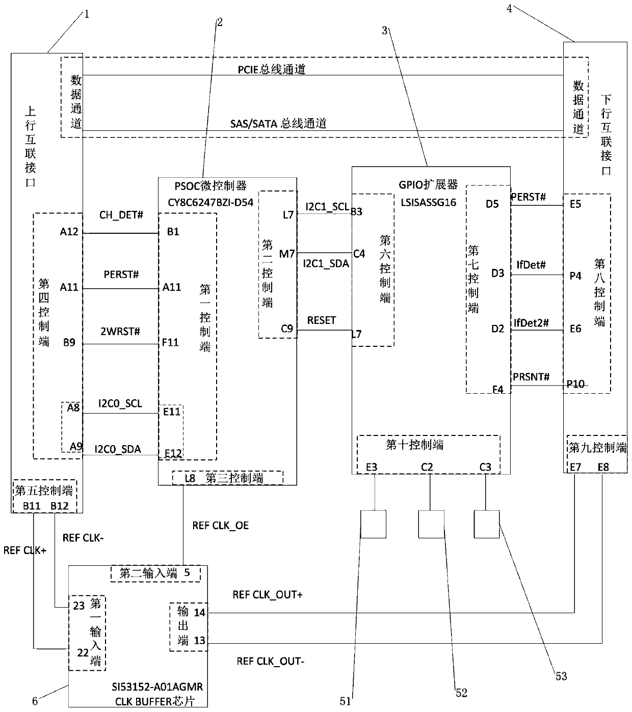
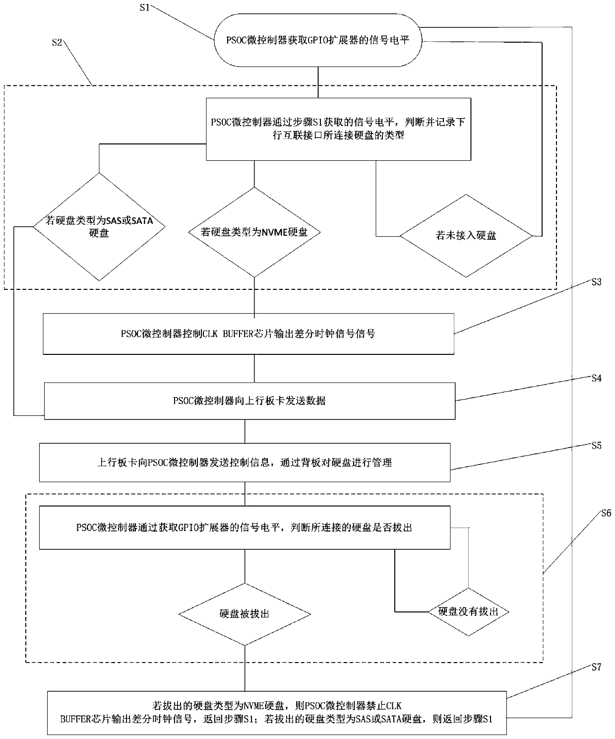
The invention provides a U.2 interface multi-hard disk management backboard and a method, and the backboard comprises a PSOC microcontroller of which the first control end is connected with the fourthcontrol end of an uplink interconnection interface; a GPIO expander of which the sixth control end is connected with the second control end of the PSOC microcontroller; a seventh control end of the GPIO expander is connected with an eighth control end of the downlink interconnection interface; a CLK BUFFER chip of which the first input end is connected with the fifth control end of the uplink interconnection interface, the second input end of the CLK BUFFER chip is connected with the third control end of the PSOC microcontroller, and the output end of the CLK BUFFER chip is connected with theninth control end of the downlink interconnection interface; a downlink interconnection interface which is connected with the uplink interconnection interface through a data channel; the downlink interconnection interface is a U.2 interface and is used for being connected with a storage medium of the U.2 interface; the U.2 hard interface hard disk is managed through the method, and safer hot plugof the NVME hard disk is achieved.

Description

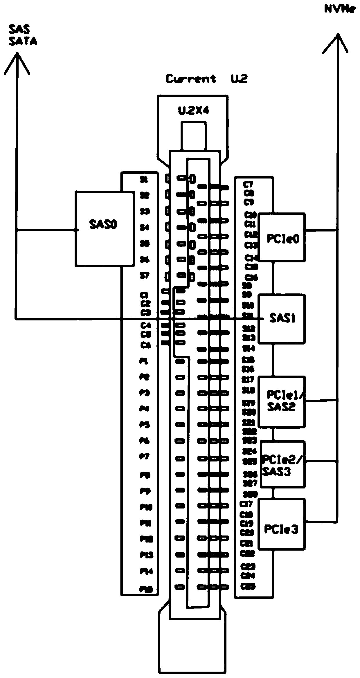
technical field [0001] The invention relates to the technical field of backplane design, in particular to a U.2 interface multi-hard disk management backplane and a method thereof. Background technique [0002] At present, hard disks using the U.2 interface standard have been widely circulated. The U.2 interface is also called SFF-8639. The U.2 interface combines the characteristics of SATA and SAS interfaces. U.2 supports the NVMe protocol and is compatible with SAS, The SATA protocol specification can connect different types of hard disks such as SAS, SATA and NVME. Among them, the interface hard disks of SAS and SATA include both mechanical hard disks (HDD) and solid-state hard disks (SSD), and NVME is a solid-state hard disk based on the NVME protocol. [0003] For different types of SAS, SATA, and NVME hard disks, their backplane management solutions are often different. For some existing backplanes, SAS and SATA hard disks use the SGPIO management scheme, and NVME hard...

Claims


Application Information

Patent Timeline
IPC IPC(8): G06F17/50G06F13/40
CPCG06F13/4081G06F30/39Y02D10/00
Inventor 付水论
Owner SUZHOU LANGCHAO INTELLIGENT TECH CO LTD
Learn More