
Color wheel component, light source system and projection device

A component and color wheel technology, applied in the field of optics, can solve problems such as inconsistency, difficulty in synchronization, brightness attenuation of red phosphors, etc., to achieve the effects of avoiding attenuation, good system effect, and solving thermal quenching

Active Publication Date: 2019-10-25
APPOTRONICS CORP LTD
View PDF8 Cites 1 Cited by
  • Summary
  • Abstract
  • Description
  • Claims
  • Application Information

AI Technical Summary

Problems solved by technology

[0004] However, in the state of high-speed rotation of the color wheel, corresponding to the adjustment of the current of the excitation light, there will be a problem of synchronization difficulties, that is, the adjustment pace of the excitation light and the red phosphor segment and the yellow / green phosphor segment of the color wheel are located on the excitation light path. may be out of step, causing problems with red phosphor brightness decay on the color wheel

Method used


Image

  • Color wheel component, light source system and projection device
  • Color wheel component, light source system and projection device
  • Color wheel component, light source system and projection device

Examples


Embodiment 1

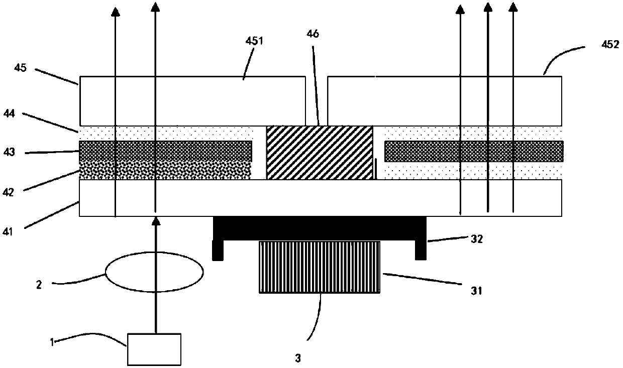
[0030] see figure 1 , The light source system of the present invention includes an excitation light source 1 , a relay lens 2 , a driving device 3 and a color wheel assembly 4 .

[0031] The excitation light source 1 is used to emit excitation light, and the excitation light is irradiated onto the color wheel assembly 4 through the adjustment of the relay lens 2 to realize wavelength conversion. The driving device 3 includes a driving motor 31 and a motor connection device 32 , and the color wheel assembly 4 rotates at a high speed driven by the driving device 3 .

[0032] The color wheel assembly 3 includes a substrate layer 41 , a first gap layer 42 , a fluorescent layer 43 , a second gap layer 44 and a filter layer 45 arranged in sequence along the irradiation direction of the excitation light.

[0033] The substrate layer 41 is made of sapphire material, and has an anti-blue and transparent yellow layer that reflects blue light and transmits yellow light.

[0034] refer ...

Embodiment 2

[0045] This embodiment is substantially the same as the first embodiment, except that in this embodiment, the boron nitride and glass frit on the first void layer 42 are sprayed on the upper surface of the substrate layer 41, wherein the boron nitride The spraying thickness is 0.01-0.050um, and the spraying thickness of the glass powder is 0.01-0.050um.

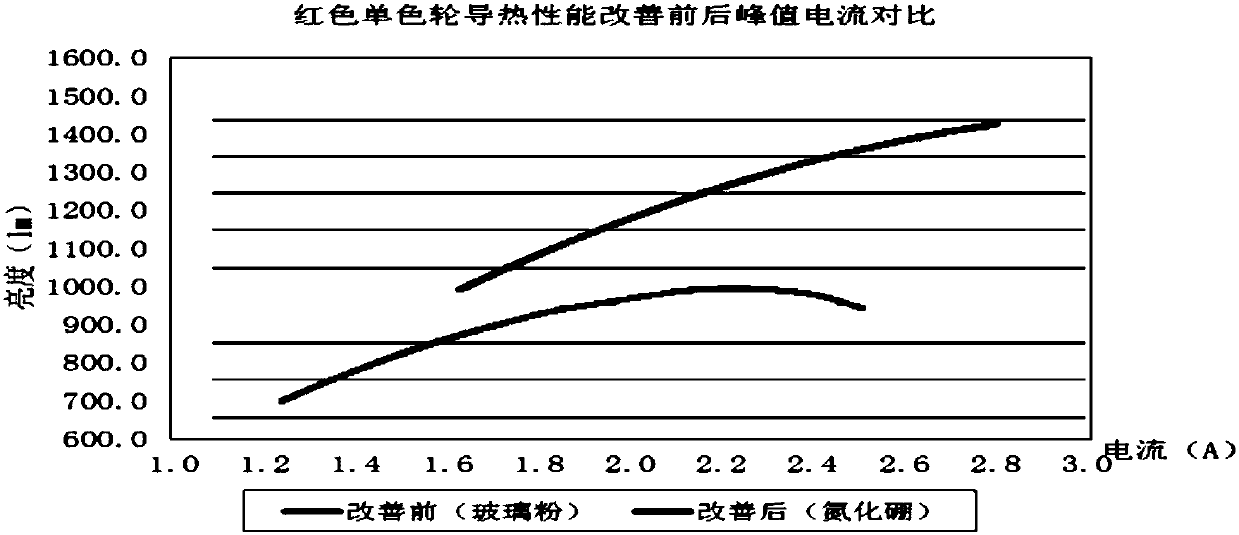
[0046] The beneficial effects of the present invention are: different from the situation of the prior art, one side of the light source system of the present invention corresponding to the red fluorescent area is provided with a boron nitride coating, the other side is provided with glass frit, and both sides of the non-red fluorescent area are uniform. Set with glass powder coating. By setting the boron nitride material at the corresponding position of the red fluorescent area, compared with the glass powder, the thermal conductivity of the boron nitride material is better, and the crystal structure of boron nitride is a lay...


PUM


Abstract

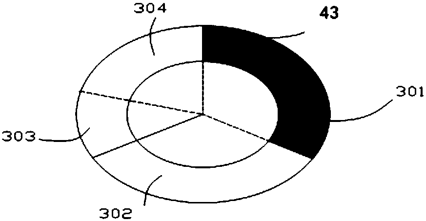
The invention provides a color wheel component, an excitation light source and a projection device. One side of a corresponding part of a red fluorescence area of the color wheel component is providedwith a boron nitride coating while the other side is provided with glass powder, and two faces of a non-red fluorescence area both are provided with glass powder coatings. Since a boron nitride material is arranged at a corresponding position of the red fluorescence area, compared with the glass powder, thermal conductivity of the boron nitride material is better, and a crystal structure of the boron nitride is a stratified structure, the boron nitride material can play a role in blocking light effectively, consequently, exciting light incident to a red fluorescence powder part can be reducedfurther, attenuation of the red fluorescence generated under direct irradiation of relatively stronger exciting light can be avoided effectively, therefore, adjustment of intensity of the exciting light specially executed for the red fluorescence powder is not needed, exciting of different fluorescence powder can be satisfied simultaneously just by keeping the same exciting light path, a problemof thermal quenching of the red fluorescence powder is solved effectively, system effects can be better, the service life is prolonged, and the production cost is reduced effectively.

Description

technical field [0001] The invention relates to the field of optics, in particular to a color wheel assembly, a light source system and projection equipment using the color wheel assembly. Background technique [0002] At present, the technology of projection equipment develops rapidly and has been widely used. In the projection equipment, the excitation light source and the wavelength conversion device are the most critical components. Usually, the wavelength conversion device is a color wheel, on which are arranged different phosphor powders that are irradiated by the excitation light in sequence, and produce different laser beams after being irradiated by the excitation light. . [0003] Because the red phosphor is excited by the excitation light with too high intensity, it is easy to produce light saturation phenomenon, that is: with the increase of the excitation light intensity, the light output of the red phosphor emitted by the red phosphor does not always increase;...

Claims


Application Information

Patent Timeline
Patent Type & Authority Applications(China)
IPC IPC(8): G02B26/00G03B21/20
CPCG02B26/008G03B21/204G02B5/00G03B33/08
Inventor 戴达炎周浩李屹
Owner APPOTRONICS CORP LTD
Learn More