Pay-off equipment for cable processing

A kind of equipment and cable technology, which is applied in the field of pay-off equipment for cable processing, can solve the problems of fixed conductor disc, broken conductor, bulky conductor disc, etc., and achieve the effect of reducing breakage and facilitating disassembly and assembly

Active Publication Date: 2021-03-30
南通远景电工器材有限公司
View PDF19 Cites 0 Cited by
  • Summary
  • Abstract
  • Description
  • Claims
  • Application Information

AI Technical Summary

Problems solved by technology

[0005] Aiming at the deficiencies in the prior art, the object of the present invention is to provide a cable processing pay-off device to solve the problem that the prior art is difficult to install directly on the pay-off device because the conductor disk is relatively heavy, and it is necessary to put down the rotating shaft and then Interspersed and fixed, and the conductor disk will rotate relative to the rotating shaft during rotation, causing the conductor disk to not move, and the subsequent strands of the conductor will be pulled back continuously, causing the conductor to break, and the impact will continue to release. line production problems

Method used


Image

  • Pay-off equipment for cable processing
  • Pay-off equipment for cable processing
  • Pay-off equipment for cable processing

Examples


specific Embodiment

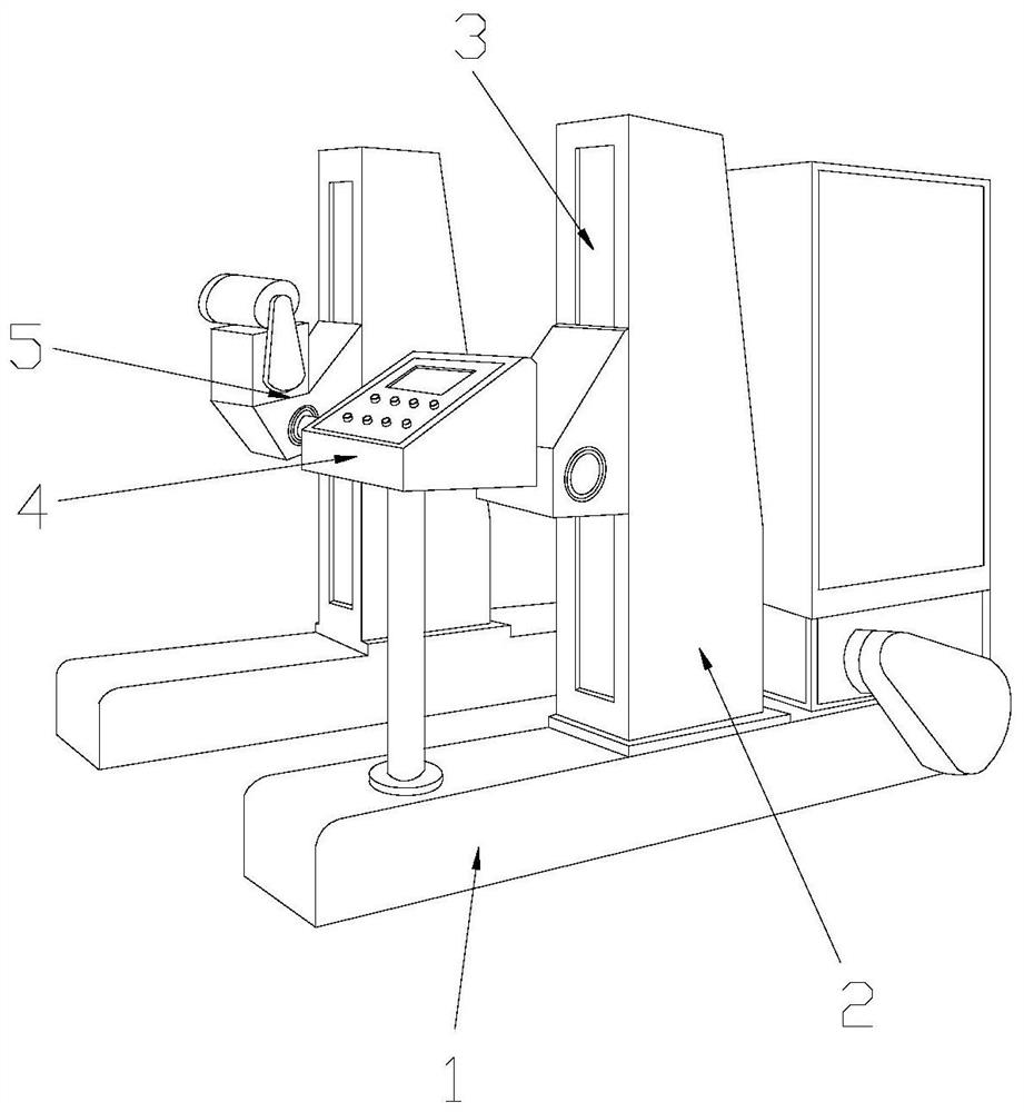
[0028] see Figure 1-Figure 10 , the specific embodiments of the present invention are as follows:

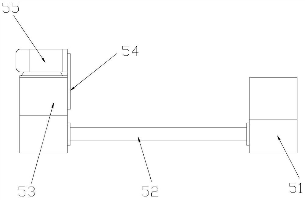
[0029] Its structure includes a load-bearing beam 1, a support beam 2, a lifting rail 3, a control box 4, and a wire release device 5. The support beam 2 is vertically installed on the upper end of the load-bearing beam 1 and welded, and the lifting rail 3 is embedded and installed on the support beam. 2, the control box 4 is arranged above the load-bearing beam 1, and the wire-releasing device 5 is installed on the front end of the supporting beam 2 and is flexibly connected with the lifting rail 3; the wire-releasing device 5 includes a driven disassembly structure 51, a wire-releasing structure 52, a transmission structure 53, a transmission belt 54, and a motor 55. The left side of the driven dismounting structure 51 is equipped with a pay-off structure 52 and adopts a flexible connection. The motor 55 is connected with the transmission structure 53 through the transmissio...


PUM


Abstract

The invention discloses paying-off equipment for cable processing. The pay-off equipment structurally comprises a bearing beam, a supporting beam, a lifting rail, a control box and a paying-off device, wherein the supporting beam is vertically arranged at the upper end of the bearing beam and is welded to the bearing beam, the lifting rail is embedded in the inner side of the supporting beam, thepaying-off device comprises a driven dismounting structure, a paying-off structure, a transmission structure, a transmission belt and a motor. According to the equipment, the paying-off structure is arranged between the driven dismounting structure and the transmission structure, an inserting rod penetrates into the inner side of a conductor roll, clamping plate structures are arranged on the twosides of the conductor roll in a sleeving mode, springs are arranged on the clamping plate structures, the right end of the inserting rod penetrates into a sleeve structure, and the left side of the inserting rod is sleeved with a driving sleeve, so that the inserting rod is completely limited, and the springs on the two sides can push the clamping plate structures to clamp the conductor roll, therelative rotation of the conductor coil is limited while dismounting is facilitated, the conductor coil can rotate along with the insertion rod better, and the phenomenon that the conductor is brokendue to the fact that the conductor does not move but twisted wire of the conductor is continuously pulled backwards is reduced.

Description

technical field [0001] The invention belongs to the field of cable processing, and in particular relates to a pay-off device for cable processing. Background technique [0002] The processing of cables is mainly divided into the manufacture of conductors, conductor strands, insulation injection molding, combined sheath injection molding, and roll packaging. When stranding conductors, the bundled conductors need to be unwound and then twisted through a stranding machine. If you use manual pay-off, the efficiency is low and the labor required for a larger reel is larger. With the development of science and technology, the current pay-off equipment for cable processing uses automatic pay-off, which improves the degree of automation and reduces labor, but the existing technology has the following deficiencies: [0003] Because the conductor disk is relatively heavy, it is not easy to install it directly on the pay-off equipment. It is necessary to put down the rotating shaft an...

Claims


Application Information

Patent Timeline
Patent Type & Authority Patents(China)
IPC IPC(8): B65H49/36B65H49/34
CPCB65H49/34B65H49/36B65H2701/341
Inventor 江泽军林兆团林燕红
Owner 南通远景电工器材有限公司
Why Eureka
Try Eureka