
A variable branch modular permanent magnet built-in external rotor hub motor for electric vehicles

A technology of electric vehicles and hub motors, applied in the field of motors, can solve the problems of high amplitude of back EMF induced by no-load in stator windings, lack of advantages in the production of modular rotors, and reduce the operating efficiency of motors, so as to enhance the magnetic concentration effect and broaden the Speed ​​range, the effect of increasing the saliency ratio

Active Publication Date: 2021-10-29
武汉研道科技有限公司
View PDF7 Cites 0 Cited by
  • Summary
  • Abstract
  • Description
  • Claims
  • Application Information

AI Technical Summary

Problems solved by technology

However, integral internal rotors do not have the production advantages of modular rotors
In addition, the built-in rotor has a strong magnetic concentration effect, and the no-load induced counter electromotive force of the stator winding has a high amplitude. Under the conventional stator winding design, it will seriously limit the speed regulation range of the motor and reduce the operating efficiency of the motor.

Method used


Image

  • A variable branch modular permanent magnet built-in external rotor hub motor for electric vehicles
  • A variable branch modular permanent magnet built-in external rotor hub motor for electric vehicles
  • A variable branch modular permanent magnet built-in external rotor hub motor for electric vehicles

Examples


Embodiment 1

[0047] As a preferred embodiment of the present invention, with reference to the attached Figure 1-10 , this example discloses:

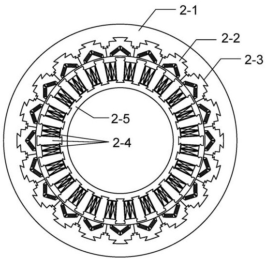
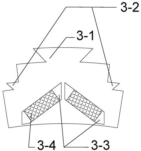
[0048] The variable branch modular permanent magnet built-in outer rotor hub motor 1 provided in this embodiment includes a stator and a rotor 1-1. The stator is located inside the motor and is composed of a stator core 1-2 and stator windings 1-3 and 1-4, and the stator core 1-2 is composed of Ns stator tooth modules 2-4 and a stator yoke 2-5 . The stator tooth module 2-4 includes a stator tooth 5-1 and a winding coil 5-2 wound on the stator tooth 5-1, which is made of laminated silicon steel sheets, and its bottom is designed as a dovetail structure 5-3; The winding coil 5-2 is formed by winding multiple turns of conductor wire. Since only one coil is wound on each stator tooth 5-1, the stator tooth module 2-4 can realize automatic winding and automatic assembly of the coil. The stator yoke 2-5 is an annular structure made of laminated silico...

Embodiment 2

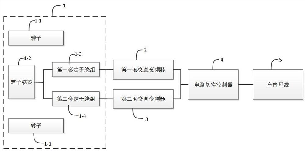
[0053] As another preferred embodiment of the present invention, with reference to the attached Figure 1-10 , this embodiment provides a variable branch modular permanent magnet built-in outer rotor hub motor 1, the number of stator winding phases m=3, the number of each phase branch k=2, the number of sets of stator windings t=2, each set The number of parallel branches per phase of the stator winding n=1. figure 1 A functional block diagram of an in-wheel motor system provided by an embodiment of the present invention is shown, and the details are as follows:

[0054] The variable branch modular permanent magnet built-in outer rotor hub motor includes an outer rotor hub motor 1, a first set of AC-DC inverter 2, a second set of AC-DC inverter 3, a circuit switching controller 4, and an in-vehicle bus 5. Wherein, the outer rotor hub motor 1 includes: a rotor 1-1, a stator core 1-2, a first set of stator windings 1-3 and a second set of stator windings 1-4.

[0055] Now in c...


PUM


Abstract

The invention discloses a variable branch modular permanent magnet built-in outer rotor hub motor for electric vehicles, and relates to the technical field of motors. The stator core of the present invention is composed of Ns stator tooth modules and a stator yoke. The stator tooth module includes a stator tooth and a winding coil wound on the stator tooth. The stator winding adopts a fractional slot concentrated winding structure to form an m-phase winding, wherein Each phase is composed of k winding branches; the m-phase windings with k winding branches are respectively controlled by t m-phase direct-alternating frequency converters, and the rotor is composed of a rim and 2p rotor core modules. The invention has the advantages of high torque / power density, large reluctance torque, widening speed regulation range by having the ability to change paths, realizing modularized manufacturing and automatic production, and the like.

Description

technical field [0001] The present invention relates to the technical field of motors, and more specifically relates to a wheel hub motor for electric vehicles, in particular to a variable branch modular permanent magnet built-in outer rotor hub motor for electric vehicles. Background technique [0002] With the rapid development of the economy and the continuous improvement of the quality of life, the automobile has become an indispensable means of transportation, playing a vital role in industry, logistics, production and daily life. At present, fuel vehicles with mature technology still occupy the absolute main force of the automobile industry, but their shortcomings are becoming more and more obvious: First, fuels such as gasoline or diesel are produced by non-renewable energy sources such as petroleum, which is inconsistent with the modern economic concept of sustainable development; Second, the exhaust gas containing carbon dioxide, nitrogen oxides, and sulfides emitte...

Claims


Application Information

Patent Timeline
Patent Type & Authority Patents(China)
IPC IPC(8): H02K1/14H02K1/27H02K1/28H02K1/02H02K3/28H02K11/33H02K21/22
CPCH02K1/02H02K1/148H02K1/2786H02K1/28H02K3/28H02K21/22H02K2213/03H02K11/33Y02T10/64
Inventor 肖洋肖海航李振兵
Owner 武汉研道科技有限公司
Learn More