
External rotor permanent magnet motor

A permanent magnet motor and external rotor technology, which is applied to the rotor and related motors, and the fixed field of the external rotor permanent magnet motor, can solve the problem that the air gap magnetic density of the concentrated winding is large, the vibration and noise are large, and the cost of the magnetic steel increases. and other problems, to achieve the effect of high winding coefficient, improved performance and low torque ripple

Inactive Publication Date: 2020-02-04
江苏迈吉易威电动科技有限公司
View PDF9 Cites 0 Cited by
  • Summary
  • Abstract
  • Description
  • Claims
  • Application Information

AI Technical Summary

Problems solved by technology

However, the more segments the magnetic steel has, the more difficult it is to assemble the motor during manufacturing, and the cost of the magnetic steel will also increase significantly
[0003] Compared with the distributed winding motor, the concentrated winding group has the advantages of small end, low cost, good manufacturability, and high efficiency. However, due to the large air gap flux density harmonics of the concentrated winding group, there are usually large torque fluctuations, vibration and Loud noise etc.

Method used


Image

  • External rotor permanent magnet motor
  • External rotor permanent magnet motor
  • External rotor permanent magnet motor

Examples


Embodiment 1

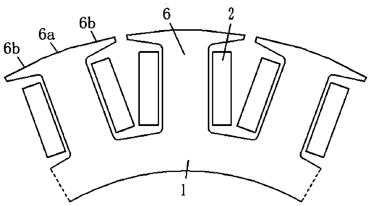
[0021] Embodiment 1: as figure 1 As shown, an outer rotor permanent magnet motor includes a stator and an outer rotor. The outer rotor includes a rotor core 3 and several rotor magnets 4 fixed inside the rotor core 3 . The stator includes a stator core 1 and a stator winding 2 embedded in the stator slot. The stator tooth 6 includes a tooth body 6a and tooth shoes 6b located on the left and right sides of the tooth body 6a. The top surfaces of the tooth body 6a and the tooth shoes 6b on the left and right sides form Segmented structure.

[0022] The relationship between the stator slot number Q and the outer rotor pole number 2P satisfies Q=2P±1 or Q=2P±2, where P is the number of rotor pole pairs. Setting the appropriate slot and pole coordination can increase the winding coefficient of the motor, increase the flux linkage of the motor, and improve the output capacity of the motor. The cross-section of the rotor magnetic steel 4 perpendicular to the motor shaft is an isosc...

Embodiment 2

[0026] Embodiment 2: The only difference from Embodiment 1 is that the top surfaces of the tooth shoes 6b on the left and right sides of a single stator tooth 6 are located on a regular polygonal structure, and the top surfaces of the tooth body 6a in the middle of the tooth shoes 6b on the left and right sides are circular arcs , the center of the arc is the motor shaft.


PUM


Abstract

The invention discloses an external rotor permanent magnet motor. The external rotor permanent magnet motor includes a stator and an external rotor; the external rotor includes a rotor iron core and aplurality of rotor steel magnets fixed inside the rotor iron core; the stator includes a stator iron core and a stator winding embedded into a stator groove; a stator tooth includes a tooth body anda tooth boot located on left and right sides of the tooth body; the tooth body and top surfaces of the tooth boots on the left and right sides form a segmented type structure; and a relationship between the number of stator grooves Q and the number of poles of the external rotor 2P meets Q=(2P+ / -1):2P, wherein the P is the number of pole pairs of the rotor. According to the external rotor permanent magnet motor, on the basis of improving performance of the motor, the difficulty of a machining process is reduced, and the manufacturing cost of the motor is reduced; and the external rotor permanent magnet motor has the advantages of high winding coefficient, small harmonic content, low torque pulsation and high torque / power density, and the like, and can be widely applied to fields such as flywheel energy storage, electromobile and electric propulsion.

Description

technical field [0001] The invention relates to the field of motors, in particular to a stator and rotor of an outer rotor permanent magnet motor with high torque density and low ripple and the related motor. Background technique [0002] The outer rotor concentrated winding permanent magnet motor has the advantages of small magnetic flux leakage coefficient and high torque density, and is widely used in various fields. However, due to the existence of the magnetic steel, when the motor is running at a higher speed, due to the change of the magnetic field, additional eddy current loss will be generated on the magnetic steel of the motor. For the eddy current loss, the most commonly used method is to adopt the method of segmenting the magnetic steel. By reducing the volume of the magnetic steel, the eddy current on the magnetic steel is reduced, thereby weakening the eddy current loss generated on the magnetic steel. The more segments the magnetic steel has, the better the e...

Claims


Application Information

Patent Timeline
Patent Type & Authority Applications(China)
IPC IPC(8): H02K1/16H02K1/27
CPCH02K1/165H02K1/2786H02K2213/03Y02T10/64
Inventor 王敏宣正骁耿伟伟施刚
Owner 江苏迈吉易威电动科技有限公司
Learn More