Vehicle profile measurement method based on vector image measurement

A vehicle profile and image measurement technology, which is applied to measurement devices, instruments, and optical devices, etc., can solve the problems of inability to provide effective guidance and suggestions for vehicle maintenance operations, inability to quantitatively measure dimensions, and high equipment failure rates. Real-time On-site picture visualization monitoring, real-time disease classification management, simple layout effect

Inactive Publication Date: 2019-10-22
GUANGZHOU AUTO TRANSPORT MEASURE & CONTROL TECH
View PDF17 Cites 8 Cited by
  • Summary
  • Abstract
  • Description
  • Claims
  • Application Information

AI Technical Summary

Problems solved by technology

Its shortcomings are: the specific size of each part cannot be quantitatively measured; a set of limit gates is only suitable for one type of vehicle; a database cannot be formed, and effective guidance and suggestions for vehicle maintenance operations cannot be given; the measurement efficiency is low
Its shortcomings are: complex mechanical structure, high failure rate of equipment operation; cumbersome mechanical adjustments for different models; low measurement efficiency
[0012] In addition, in the stage of vehicle frame, overhaul and static commissioning, it is also necessary to measure the position and size of various parts such as the vehicle power receiving area, bogie, pneumatic, brake and drive motors. At present, most of them still use manual measurement methods , low work efficiency

Method used


Image

  • Vehicle profile measurement method based on vector image measurement
  • Vehicle profile measurement method based on vector image measurement
  • Vehicle profile measurement method based on vector image measurement

Examples


Embodiment Construction

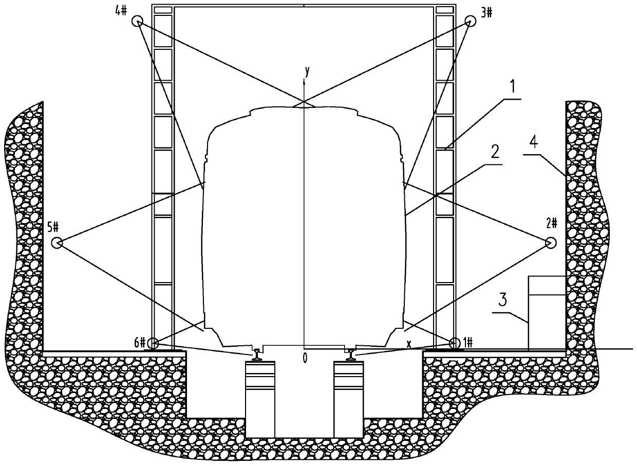
[0043] A vehicle profile measurement method based on vector image measurement in the present invention, such as figure 1 As shown, the side wall 4 of the tunnel in the detection area is provided with a limited detection cabinet 3 and a vehicle boundary line 2 . Define the space vector measurement coordinate system: the x-axis points to the positive direction of the paper, indicating the direction of travel of the train; the x-axis rotates 90° counterclockwise, which is the positive direction of the y-axis; the y-axis rotates 90° clockwise, which is the positive direction of the z-axis .

[0044] Several definitions:

[0045] Object outline: CJJ / T 96-2018 "Metro Gauge Standard" stipulates the three-dimensional coordinate values ​​of the outline points in the spatial coordinate system (referenced by the rail plane and center line); and eliminates the influence of dynamic settlement and lateral offset of the track.

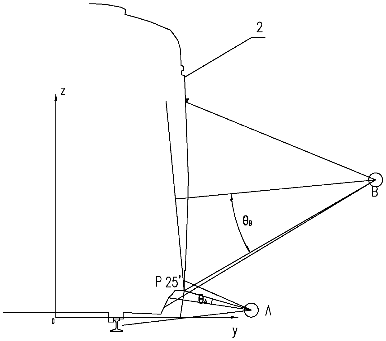
[0046] Line array plane: the angle between the length directi...


PUM


Abstract

The invention discloses a vehicle profile measurement method based on vector image measurement. The method comprises a step of installing line scan cameras at left and right sides of upper and middleparts of left and right top angle lines and left and right bottom angle lines of a vehicle profile line near a track in a detection area to form left and right linear arrays of an upper part, a middlepart and a lower part, a step of establishing a space vector measurement coordinate system with a train traveling direction as an X axis position direction and setting an X direction standard rule inan X axis, a step of setting the linear arrays in a way that one of the upper right linear array and left linear array is in front and the other one is behind the one, one of the middle right lineararray and left linear array is in front and the other one is behind the one, and the coordinates of two linear arrays in front or back in the X direction are the same and two parallel measurement sections are formed, wherein the X direction distance of the two parallel measurement sections is a nominal value of a standard ruler, and a lower measurement section formed by the lower left and right linear arrays is located in the middle of the two parallel measurement sections. According to the invention, the moving speed of the train can be accurately through the standard ruler to track the sampling line frequencies of the line scan cameras, the undistorted sampling with a high speed can be achieved, and the accurate measurement is achieved.

Description

technical field [0001] The invention relates to a vehicle profile measurement method based on vector image measurement. Background technique [0002] With the rapid development of domestic rail transit, various detection technologies around rail transit, especially high-speed and high-precision camera technology and image processing technology have become a development trend. Vehicle outline dimensions and boundaries have always been an important guarantee for safe train operation. The latest "Metro Gauge Standard" CJJ / T 96-2018 clarifies the boundaries of vehicle boundaries, tunnel equipment, platforms, screen doors, longitudinal evacuation platforms and tunnel buildings Standards and testing indicators are as follows: [0003] [0004] (Table 1) [0005] At present, the effectiveness of various industrial image detection is far from reaching the level of consumer image recognition. For example, the defect process of using image mosaic to directly compare with the sta...

Claims


Application Information

Patent Timeline
IPC IPC(8): G01B11/24
CPCG01B11/24
Inventor 邹至刚
Owner GUANGZHOU AUTO TRANSPORT MEASURE & CONTROL TECH
Why Eureka
Try Eureka