
A 3D printing molding method using continuous fibers and the target structure and application obtained by molding

A 3D printing, continuous fiber technology, applied in the field of target structures, which can solve the problems of difficult molding and inability to 3D printing and manufacturing.

Active Publication Date: 2021-07-06
AEROSPACE INST OF ADVANCED MATERIALS & PROCESSING TECH
View PDF14 Cites 0 Cited by
  • Summary
  • Abstract
  • Description
  • Claims
  • Application Information

AI Technical Summary

Problems solved by technology

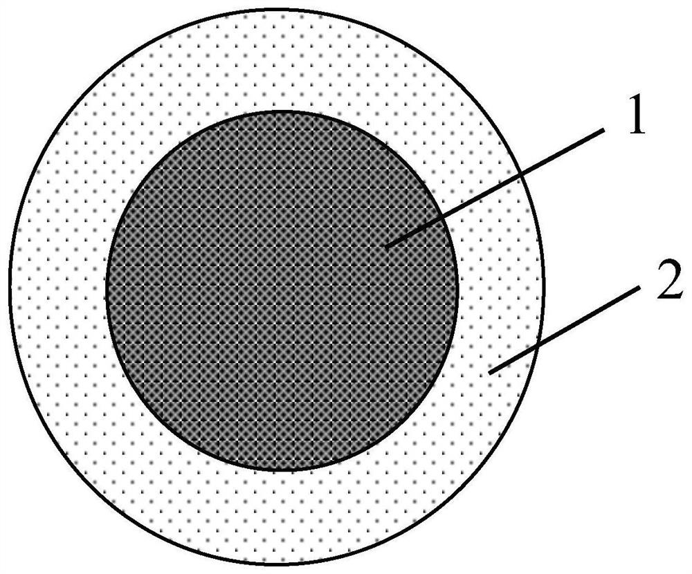
Aiming at the special target structure and the characteristics of the printing process, the present invention takes materials as the main research direction, and proposes a printing method and corresponding Print the design style of the nozzle to solve the current problem of special target structures such as (bionic composite airfoil) "excellent performance but difficult to form and cannot be 3D printed and manufactured"

Method used


Image

  • A 3D printing molding method using continuous fibers and the target structure and application obtained by molding
  • A 3D printing molding method using continuous fibers and the target structure and application obtained by molding
  • A 3D printing molding method using continuous fibers and the target structure and application obtained by molding

Examples


Embodiment 1

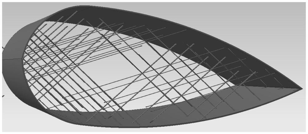
[0060] Use glass fiber + PA6 material (thermoplastic material) pre-impregnated with medium-temperature epoxy resin (thermosetting resin) as the printing tow to print the biomimetic composite airfoil:

[0061] Temperature setting: The temperature of the print head is based on the TGA test value, and the instantaneous curing temperature of the epoxy resin is 300°C. The printing speed of the parts except the corner parts is 0.5s, and the printing speed of the corner parts is 0.7s.

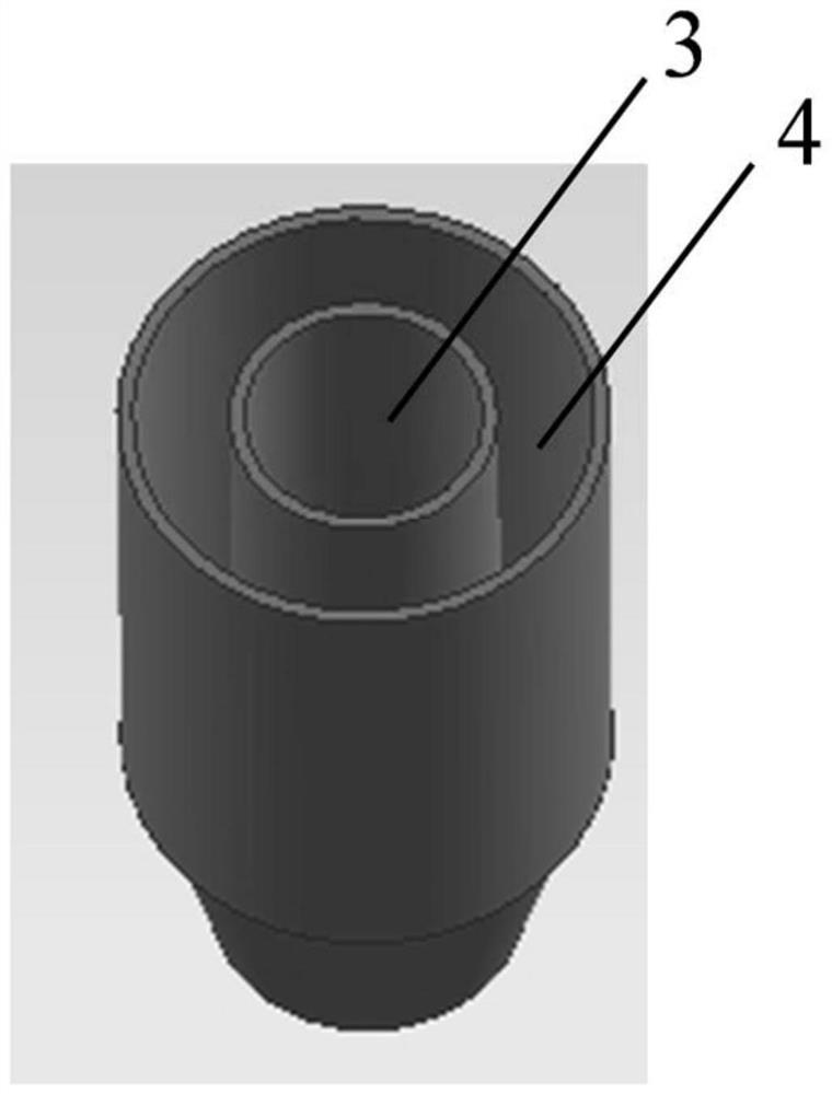
[0062] The size of the printing nozzle: the cross-sections of the inner channel and the outer channel are circular, the diameter of the inner channel is 0.4mm, and the diameter of the outer channel is 0.6mm.

[0063] According to the airfoil diagram of the airfoil of the biomimetic composite material to be printed, the printing tow in this embodiment is used as the printing consumable for 3D printing such as figure 2 The biomimetic composite airfoil shown; this embodiment can meet the design requirem...

Embodiment 2

[0065] Use carbon fiber + PVC material (thermoplastic material) pre-impregnated with unsaturated resin (thermosetting resin) as the printing tow to print the biomimetic composite airfoil:

[0066] Temperature setting: The temperature of the print head is based on the TGA test value. The instantaneous curing temperature of the unsaturated resin is 200°C. The printing speed of the parts except the corner parts is 0.5s, and the printing speed of the corner parts is 0.7s.

[0067] The size of the printing thermal nozzle: the cross-sections of the inner channel and the outer channel are both rectangular, the size of the inner channel is 0.4×0.2mm, and the size of the outer channel is 0.5×0.3mm.

[0068] According to the airfoil diagram of the airfoil of the biomimetic composite material to be printed, the printing tow in this embodiment is used as the printing consumable for 3D printing such as figure 2 The bionic composite airfoil shown; this embodiment can meet the structural de...


PUM

PropertyMeasurementUnit
diameteraaaaaaaaaa

Abstract

The invention relates to a 3D printing molding method using continuous fibers, as well as the target structure and application obtained by molding. The method is as follows: (1) providing continuous fibers pre-impregnated with thermosetting resin; (2) coating thermoplastic material on the surface of the continuous fibers to form printing tows; (3) using the printing tows by 3D printing method prints out the target structure. The present invention proposes a 3D printing method using printing filaments formed with "thermosetting material as the skeleton and thermoplastic material as the auxiliary" as consumables, which solves the problem of current target structures such as bionic airfoils "excellent in performance but difficult to form and cannot be manufactured". ; The present invention is a new form of printing method proposed on the basis of the original printing process, which is helpful to the process molding of various similar structures, and opens a new way for the forming of special structures.

Description

technical field [0001] The invention belongs to the technical field of composite material manufacturing, and in particular relates to a 3D printing molding method using continuous fibers and the target structure and application obtained by molding. Background technique [0002] Printed parts made of thermosetting materials or thermoplastic materials have the advantages of customization, no mold assistance, short molding cycle, and highly visible drawings. Large restrictions, generally used for jewelry, toys and other non-structural parts, it is difficult to meet the needs of aerospace, automotive and other high-end markets; similarly, the printing process is also subject to great constraints. In order to compensate for the shortcomings of the polymer printing process, a continuous fiber 3D printing process using continuous fiber as a reinforcement material was formed by referring to the characteristics of the automatic laying process. The materials are similar, and graduall...

Claims


Application Information

Patent Timeline
Patent Type & Authority Patents(China)
IPC IPC(8): B29C64/118B29C64/209B33Y10/00B33Y30/00B33Y70/10B33Y80/00
CPCB33Y10/00B33Y30/00B33Y70/00B29C64/118B29C64/209
Inventor 毕向军唐中华张帅赵亮赵宏杰
Owner AEROSPACE INST OF ADVANCED MATERIALS & PROCESSING TECH
Learn More