
Assembled steel column base with controllable damage

An assembly type, steel column technology, applied in the direction of columns, pier columns, pillars, etc., can solve the problems of dissipating earthquake energy, economic loss, large plastic deformation of anchor bolts, etc., to achieve improved repair ability, strong energy consumption, and damage controllable effect

Pending Publication Date: 2019-10-18
DALIAN UNIV OF TECH
View PDF0 Cites 2 Cited by
  • Summary
  • Abstract
  • Description
  • Claims
  • Application Information

AI Technical Summary

Problems solved by technology

Large deformation will occur when the anchor bolt is damaged, and the energy consumption of the column foot is mainly provided by the anchor bolt. The hysteresis curve of the column foot is not full and has obvious pinching characteristics, which is not conducive to dissipating seismic energy;
[0006] (2) The column foot is seriously damaged and cannot be repaired quickly
Since the anchor bolts are prone to large plastic deformation or even fracture, it is difficult to quickly repair on site after the earthquake, which is not conducive to the smooth progress of post-disaster reconstruction work.
Many earthquake disasters have shown that after the earthquake damage, the anchor bolts have been completely broken, and the entire column foot has irreparable damage, resulting in huge economic losses.
[0007] (3) Unable to meet disaster prevention needs based on "resilience"
It is far from enough for the existing exposed steel column foot design to only take life safety as the seismic design goal, and the functional recoverability of the column foot after an earthquake is equally important
The existing exposed steel column feet cannot meet the earthquake resistance requirements of "toughness" disaster prevention and "recoverable functional structure"

Method used


Image

  • Assembled steel column base with controllable damage
  • Assembled steel column base with controllable damage
  • Assembled steel column base with controllable damage

Examples


Embodiment 1

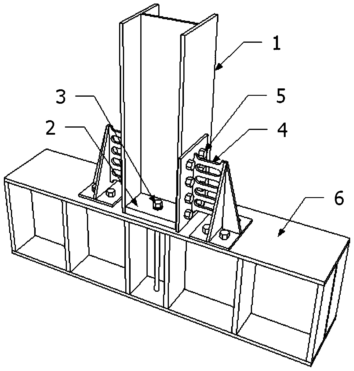
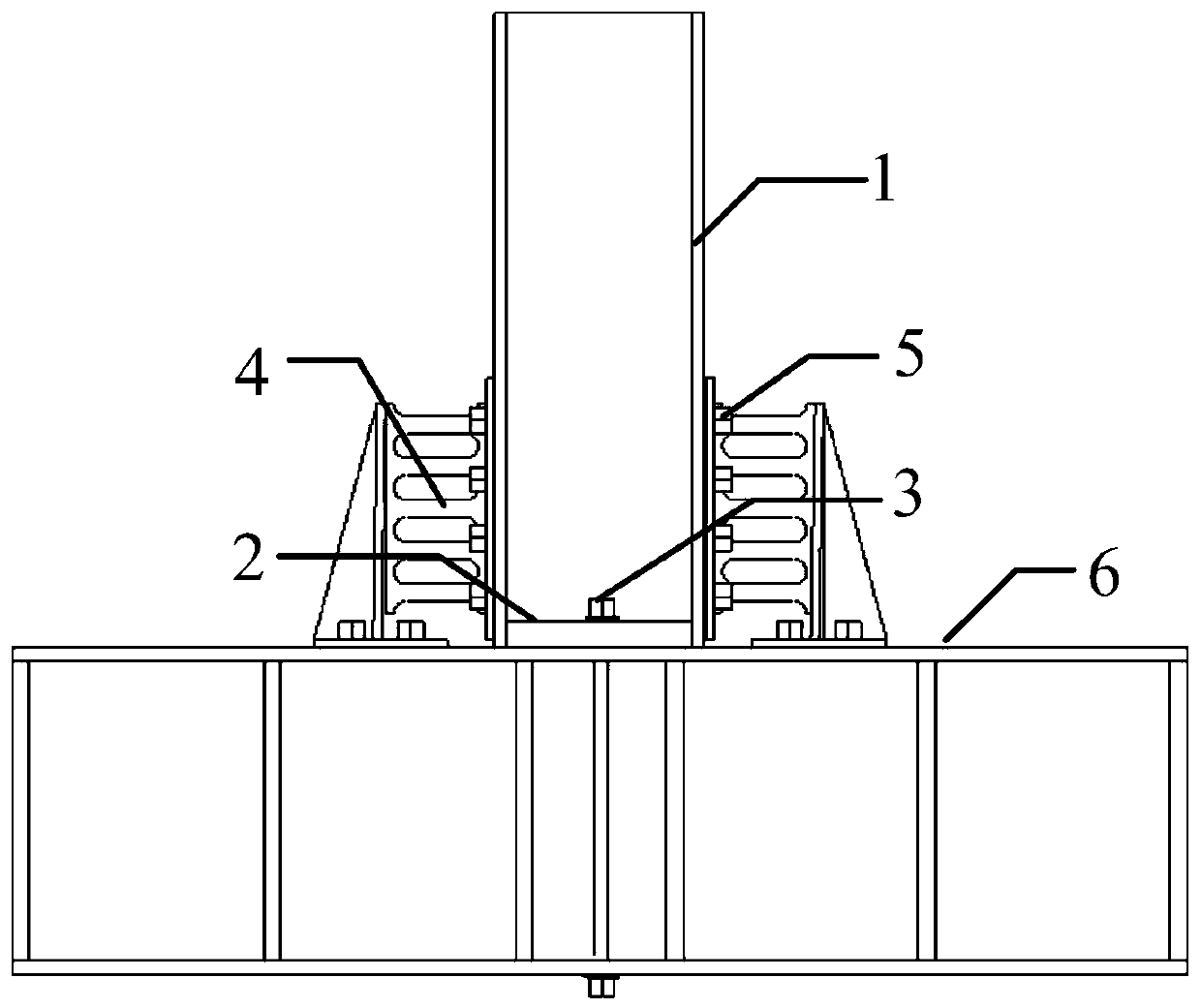
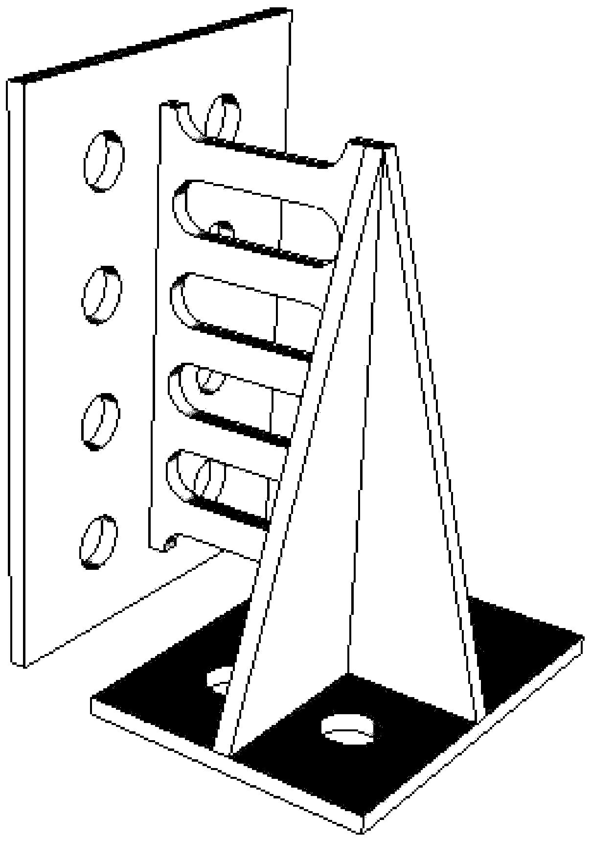
[0040] An assembled damage-controllable shear-type steel column base, including steel foundation 6, anchor bolt 3, shear-type energy dissipator 4 and steel column 1, steel foundation 6 and steel column 1 bottom plate are provided with openings, anchor bolts 3 Pass through the openings of the steel foundation 6 and the steel column bottom plate 2 and connect the steel foundation 6 and the steel column 1. The steel foundation 6 and the flange of the steel column 1 are also provided with openings according to the size of the shear energy dissipator 4, and the shear energy dissipator 4 is connected with the steel foundation 6 and the flange of the steel column 1 through high-strength bolts 5; The anchoring length of the anchor bolt 3 is not less than 25d, where d is the diameter of the anchor bolt, ensuring that the anchor bolt 3 has sufficient anchoring length and deformation capacity, and the yield strength of the shear energy dissipator 4 is less than or equal to the steel colum...

Embodiment 2

[0049] An assembled damage-controllable tension-compression steel column base, including steel foundation 6, anchor bolt 3, tension-compression energy dissipator 7 and steel column 1, steel foundation 6 and steel column 1 bottom plate are provided with openings, anchor bolts 3 Pass through the openings of the steel foundation 6 and the steel column bottom plate 2 and connect the steel foundation 6 and the steel column 1. The steel foundation 6 and the flange of the steel column 1 are also provided with openings according to the size of the tension-compression energy dissipator 7, and the tension-compression energy dissipator 7 is connected with the steel foundation 6 and the flange of the steel column 1 through high-strength bolts 5; The anchoring length of the anchor bolt 3 is not less than 25d, where d is the diameter of the anchor bolt, ensuring that the anchor bolt 3 has sufficient anchoring length and deformation capacity, and the yield strength of the tension-compression ...

Embodiment 3

[0058] An assembled damage-controllable corner braced steel column foot, including steel foundation 6, anchor bolt 3, corner brace type energy dissipator 8 and steel column 1, steel foundation 6 and steel column 1 bottom plate are provided with openings, anchor bolts 3 Pass through the openings of the steel foundation 6 and the steel column bottom plate 2 and connect the steel foundation 6 and the steel column 1. The steel foundation 6 and the flange of the steel column 1 are also provided with openings according to the size of the corner brace type energy dissipator 8, and the corner brace type energy dissipator 8 is connected with the steel foundation 6 and the flange of the steel column 1 through high-strength bolts 5; The anchoring length of the anchor bolt 3 is not less than 25d, where d is the diameter of the anchor bolt, ensuring that the anchor bolt 3 has sufficient anchoring length and deformation capacity, and the yield strength of the corner brace type energy dissipa...


PUM

PropertyMeasurementUnit
Anchorage lengthaaaaaaaaaa

Abstract

The invention belongs to the technical field of seismic resistance of building engineering, and provides an assembled steel column base with controllable damage. The steel column base includes a steelfoundation, an anchor bolt, a steel column bottom plate, energy absorbers and a steel column. On the premise of ensuring the bearing capacity and the rigidity of an exposed steel column base, the assembled exposed steel column base with controllable damage and quick replacement of the energy absorbers is provided by arranging the energy absorbers. The steel column base of the invention has the advantages of strong energy consumption capacity and controllable damage, can control the damage to exposed parts which can be easily repaired and replaced such as the energy absorbers and can improve the repairing capacity of the column base after an earthquake. After the earthquake, the energy absorbers can be quickly replaced to realize local quick repair. The column base has the advantages of easy construction, strong energy dissipation capacity in the earthquake and controllable damage and can be quickly repaired.

Description

technical field [0001] The invention belongs to the technical field of anti-seismic construction engineering, and in particular relates to an assembled steel column foot with controllable damage. Background technique [0002] The column foot is an important node connecting the superstructure and the foundation, and its seismic capacity seriously affects the performance of the overall building structure. Earthquake damage investigations at home and abroad show that the lack of bearing capacity and deformation capacity of connection nodes is one of the main reasons for steel structures to suffer earthquake damage. There are mainly two types of steel column feet: exposed type and embedded type. Due to the advantages of convenient installation and low cost, the exposed column feet are widely used in low- and medium-rise buildings. [0003] However, the existing statistical data show that if the exposed steel column foot is designed according to the current code, the deformatio...

Claims


Application Information

Patent Timeline
IPC IPC(8): E02D27/42E04C3/32E04B1/98E04H9/02
CPCE02D27/42E04C3/32E04H9/021
Inventor 崔瑶李浩王枫智
Owner DALIAN UNIV OF TECH
Learn More