Detector fully differential circuit based on charge amplification
A technology of charge amplification circuit and voltage amplification circuit, which is applied in the field of detector full differential circuit, can solve the problems of cable resistance and distributed capacitance loss, interference, noise and zero drift aggravation, so as to resist noise interference and improve low frequency reception capability, the effect of high common-mode rejection ratio
- Summary
- Abstract
- Description
- Claims
- Application Information
AI Technical Summary
Problems solved by technology
Method used
Image
Examples
Embodiment 1
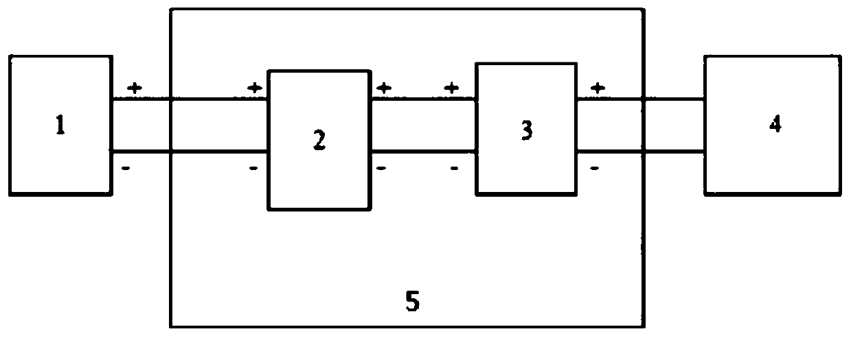
[0030] according to Figure 1-7The shown a kind of detector full differential circuit based on charge amplification includes at least core unit 1 and subsequent filtering and acquisition circuit 4, and also includes a charge amplification circuit; The output positive pole is connected, the input negative pole of the charge amplification circuit is connected with the output negative pole of the core unit 1; the output positive pole of the charge amplification circuit is connected with the input positive pole of the follow-up filtering and acquisition circuit 4, and the output negative pole of the charge amplification circuit is connected with the follow-up filtering and the negative input of the acquisition circuit 4 are connected.
[0031] Preferably, the charge amplification circuit is composed of a charge conversion circuit 2 and a voltage amplification circuit 3; the input positive pole of the charge conversion circuit 2 is connected with the output positive pole of the cor...
Embodiment 2
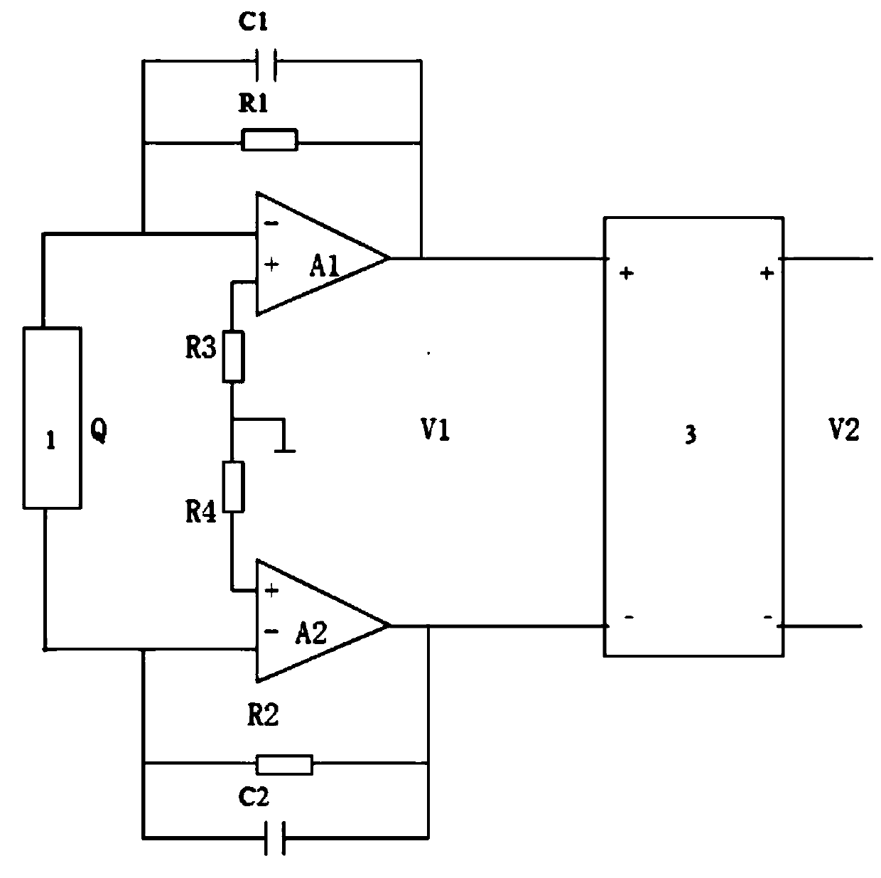
[0034] according to figure 1 , Figure 5 with Image 6 The difference between the fully differential detector circuit based on charge amplification and the first embodiment is that the charge conversion circuit 2 is composed of a first operational amplifier A1, a second operational amplifier A2, a first feedback capacitor C1, Composed of the second feedback capacitor C2, the first feedback resistor R1, the second feedback resistor R2, the first grounding resistor R3 and the second grounding resistor R4; the inverting input terminals of the first operational amplifier A1 and the second operational amplifier A2 Connected to the output of the core unit 1; one end of the first feedback capacitor C1 connected in parallel with the first feedback resistor R1 is connected to the inverting input terminal of the first operational amplifier A1, and the first feedback capacitor C1 is connected in parallel with the first feedback resistor R1 The other end is connected to the inverting ou...
Embodiment 3
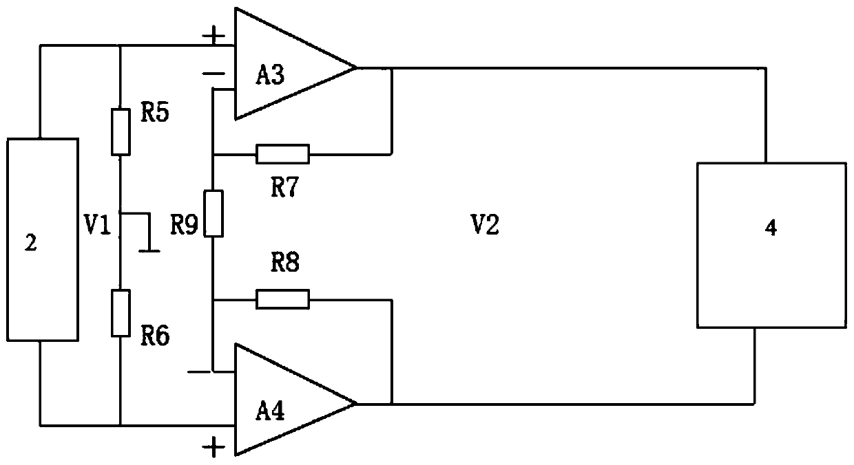
[0045] according to figure 1 with Figure 7 The difference between the fully differential detector circuit based on charge amplification and the second embodiment is that the charge conversion circuit 2 is composed of a first operational amplifier A1, a second operational amplifier A2, a first feedback capacitor C1, Composed of the second feedback capacitor C2, the first feedback resistor R1, the second feedback resistor R2, the first grounding resistor R3 and the second grounding resistor R4; the inverting input terminals of the first operational amplifier A1 and the second operational amplifier A2 Connected to the output of the core unit 1; one end of the first feedback capacitor C1 connected in parallel with the first feedback resistor R1 is connected to the inverting input terminal of the first operational amplifier A1, and the first feedback capacitor C1 is connected in parallel with the first feedback resistor R1 The other end of the second feedback capacitor C2 is conn...
PUM
 Abstract
Description
Claims
Application Information
 - R&D
- Intellectual Property
- Life Sciences
- Materials
- Tech Scout
- Unparalleled Data Quality
- Higher Quality Content
- 60% Fewer Hallucinations
Browse by: Latest US Patents, China's latest patents, Technical Efficacy Thesaurus, Application Domain, Technology Topic, Popular Technical Reports.
© 2025 PatSnap. All rights reserved.Legal|Privacy policy|Modern Slavery Act Transparency Statement|Sitemap|About US| Contact US: help@patsnap.com


