
Intermediary electric constant low temperature cofiring ceramic material and preparation method

A low-temperature co-fired ceramic and electrical constant technology, applied in the field of ceramic materials, can solve the problems of difficult grinding and fine processing, high energy consumption, low melting point glass composition and complex process, and achieve stable resonant frequency temperature coefficient and resonant frequency temperature coefficient. Small, suitable for mass production

Active Publication Date: 2019-10-11
BEIJING YUANLIU HONGYUAN ELECTRONICS TECH
View PDF8 Cites 1 Cited by
  • Summary
  • Abstract
  • Description
  • Claims
  • Application Information

AI Technical Summary

Problems solved by technology

However, chemical synthesis methods and the use of ultra-fine powders can lead to complex processes, and a sharp increase in manufacturing cycle and cost
In comparison, adding low-melting glass, compounds or oxides that match the material matrix will lead to a decrease in the microwave performance of the matrix material, but the process is simple and easy to achieve industrial production
However, the composition and process of low-melting point glass are relatively complicated, and the production cost is high. Professional equipment is required for high-temperature melting of glass, which takes a long time for heat treatment and consumes a lot of energy.
Moreover, the cold quenching process of glass has a large loss of equipment, the glass slag after quenching has high hardness, it is difficult to grind, the shape of the glass is poor, and the process adaptability is not good
Low melting point oxides, such as V2O5 and B2O3, although they can effectively reduce the Sintering temperature, but it is very easy to react with organic additives such as PVA and PVB in the process of gelation, which affects the production of ceramic cast film belts

Method used


Image

  • Intermediary electric constant low temperature cofiring ceramic material and preparation method
  • Intermediary electric constant low temperature cofiring ceramic material and preparation method
  • Intermediary electric constant low temperature cofiring ceramic material and preparation method

Examples


Embodiment

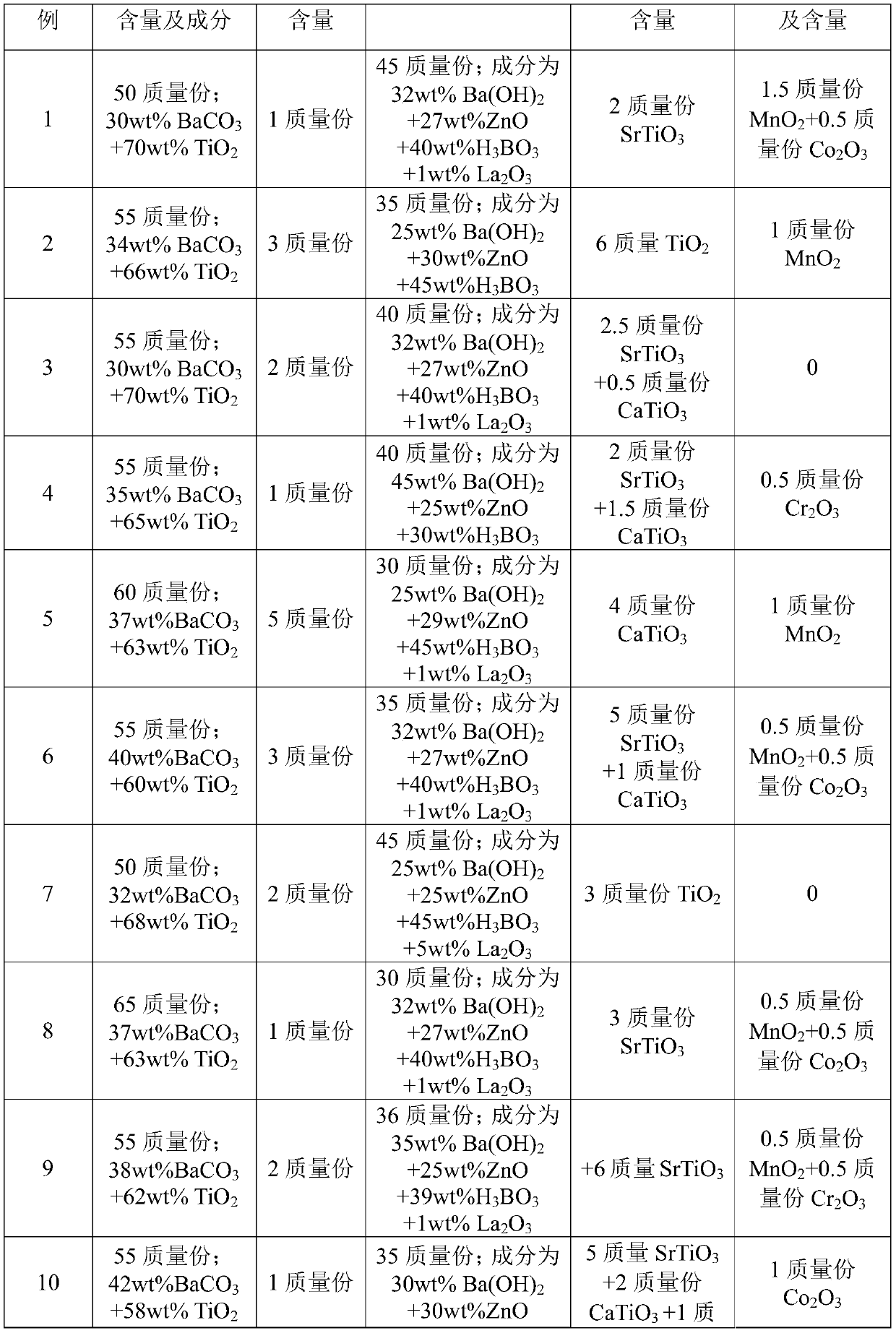
[0019] The present invention calculates the formula according to the number of parts by mass, using solid-phase synthesized Ba-Ti compound, powder A, powder B, powder C and analytically pure powder D, specific examples are shown in Table 1. Among them, the Ba-Ti compound is a calcined body, which consists of 30 to 50 parts by mass of BaCO 3 and 50-70 parts by mass of TiO 2 composition. Powder A is calcined body, its chemical composition is BaZn 2 Ti 4 o 11 . Powder B is a calcined body, and its composition is 20 to 45 parts by mass of Ba(OH) 2 , 20-40 parts by mass of H 3 BO 3 , 25-50 parts by mass of ZnO and 0-5 parts by mass of La 2 o 3 . The powder C is SrTiO 3 、TiO 2 and CaTiO 3 one or more of. The powder D is MnO 2 、Co 2 o 3 and Cr 2 o 3 one or more of.

[0020] In Table 1, the synthesis temperature of Ba-Ti compound is 1150℃, BaCO 3 and TiO 2 The relative mass parts of the powder A are shown in Table 1, and other mass parts and other synthesis tempe...


PUM


Abstract

The invention discloses an intermediary electric constant low temperature cofiring ceramic material and a preparation method, wherein the ceramic material comprises 50-70 parts by weight of a Ba-Ti compound, 0-5 parts by weight of powder A, 30-45 parts by weight of powder B, 2-15 parts by weight of powder C and 0-2 parts by weight of powder D; wherein the Ba-Ti compound comprises BaCO3 and TiO2, the powder A is BaZn2Ti4O11, the power B comprises Ba(OH)2, H3BO3, ZnO and La2O3, the ingredient(s) of the powder C is / are one or a plurality of SrTiO3, TiO2 and CaTiO3, and the powder D is one or a plurality of MnO2, Co2O3 and Cr2O3. By the technical scheme of the invention, the intermediary electric constant low temperature cofiring ceramic material obtains a relatively excellent ceramic microwave characteristic, is simple in preparation process and suitable for large-scale production, has good compatibility with a microwave matrix material, and lowers the sintering temperature of materials effectively.

Description

technical field [0001] The invention relates to the technical field of ceramic materials, in particular to a low-temperature co-fired ceramic material with a medium dielectric constant and a preparation method thereof. Background technique [0002] Low temperature co-fired ceramic (Low Temperature Co-fired ceramic, LTCC) technology, as an electronic component integration technology, adopts a multi-layer wiring structure, which can realize passive components (resistors, capacitors, inductors, filters, resonances) on a three-dimensional structure. Couplers) and transmission lines can also be surface-mounted IC components, so that the device can achieve high integration and functional compounding on the basis of maintaining excellent high-frequency characteristics, and can meet the requirements of future electronic equipment development. LTCC microwave passive components have low dielectric loss, high operating frequency (up to 40GHz), small size, and high stability in harsh en...

Claims


Application Information

Patent Timeline
Patent Type & Authority Applications(China)
IPC IPC(8): C04B35/468C04B35/622C04B35/64C04B35/626
CPCC04B35/4682C04B35/622C04B35/64C04B35/62605C04B2235/3284C04B2235/3227C04B2235/3409C04B2235/3236C04B2235/3213C04B2235/3267C04B2235/3275C04B2235/3208C04B2235/3232C04B2235/6562C04B2235/656C04B2235/96
Inventor 齐世顺程华容宋蓓蓓杨魁勇孙淑英
Owner BEIJING YUANLIU HONGYUAN ELECTRONICS TECH
Learn More