UV LED all-inorganic packaging structure with prompt function
A technology of reminder function and packaging structure, which is applied in the direction of electrical components, electrical solid devices, circuits, etc., can solve the problems of lack of integrated products with UV functions, can not see light, etc., and achieve the effect of enhancing stability and improving working life
- Summary
- Abstract
- Description
- Claims
- Application Information
AI Technical Summary
Problems solved by technology
Method used
Image


Examples
Embodiment 1
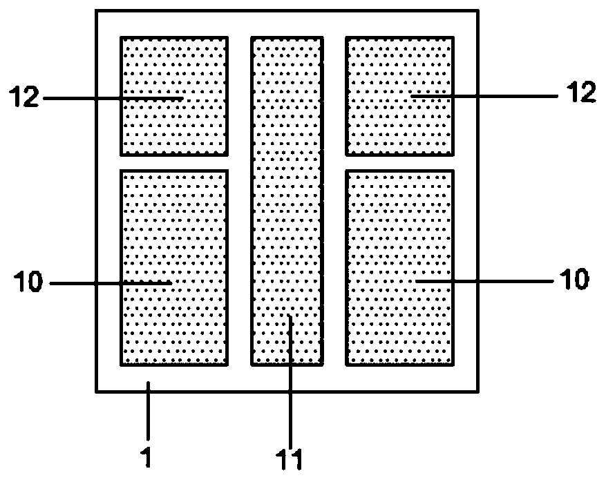
[0027] Substrate 1 is an alumina substrate, which is pre-treated and cleaned, and then 2 through-hole pairs are drilled on the alumina substrate by laser, and the 2 through-hole pairs are arranged side by side, and the through-holes are filled with conductive metal by sputtering Yes, the conductive metal is copper, and a conductive metal layer with a thickness of 10 μm is formed on the upper and lower surfaces of the substrate.
[0028] Such as figure 1 and figure 2 As shown, the upper surface and the lower surface of the substrate 1 are covered with photoresist by means of yellow light lithography, and after the photoresist covers the substrate 1, exposure, development, etching, and film removal are performed. The uncovered area on the upper surface forms pad pair 1 3 and pad pair 4 , the area below pad pair 3 and the uncovered area on the lower surface of substrate 1 forms electrode pair 10 , pad pair 2 4 below, and the substrate 1 The uncovered area of the lower surfac...
Embodiment 2
[0036] Such as Figure 5 As shown, the substrate 1 is an aluminum nitride substrate, which is pre-treated and cleaned, and then a through-hole pair is drilled on the aluminum nitride substrate by deep reactive ion etching, and the conductive metal is filled with the through-hole pair by sputtering. The conductive metal is copper, and a conductive metal layer with a thickness of 1000 μm is formed on the upper and lower surfaces of the substrate.
[0037] Such as Figure 5 and Figure 6 As shown, the upper surface and the lower surface of the substrate 1 are covered with photoresist by means of yellow light lithography, and after the photoresist covers the substrate 1, exposure, development, etching, and film removal are performed. The uncovered area on the upper surface forms a pair of pads 3 14, the area below the pair of pads and the uncovered area on the lower surface of the substrate forms an electrode pair 3 16, and a thermoelectric separation structure 11 is formed betw...
Embodiment 3
[0042] Such as Figure 7 As shown, substrate 1 is an aluminum nitride substrate, which is pre-treated and cleaned, and then 2 pairs of through holes are drilled on the aluminum nitride substrate by deep reactive ion etching, and the 2 pairs of through holes are arranged side by side. The method is to fill the pair of through holes with conductive metal, the conductive metal is copper, and a conductive metal layer with a thickness of 650 μm is formed on the upper and lower surfaces of the substrate 1 respectively.
[0043] Such as figure 2 As shown, the upper surface and the lower surface of the substrate 1 are covered with photoresist by means of yellow light lithography, and after the photoresist covers the substrate 1, exposure, development, etching, and film removal are performed. The uncovered area on the upper surface forms pad pair one 3 and pad pair two 4, the area below pad pair one 3 and the uncovered area on the lower surface of the substrate forms electrode pair o...
PUM
 Abstract
Description
Claims
Application Information
 - Generate Ideas
- Intellectual Property
- Life Sciences
- Materials
- Tech Scout
- Unparalleled Data Quality
- Higher Quality Content
- 60% Fewer Hallucinations
Browse by: Latest US Patents, China's latest patents, Technical Efficacy Thesaurus, Application Domain, Technology Topic, Popular Technical Reports.
© 2025 PatSnap. All rights reserved.Legal|Privacy policy|Modern Slavery Act Transparency Statement|Sitemap|About US| Contact US: help@patsnap.com