Transformation method for making motors never have bar breaking fault
A technology of broken bars and motor rotors, applied in the manufacture of motor generators, asynchronous induction motors, electromechanical devices, etc., can solve the problem of no motor broken bars and other problems, and achieve the effects of large starting torque, prevention of broken bars, and good heat dissipation.
- Summary
- Abstract
- Description
- Claims
- Application Information
AI Technical Summary
Problems solved by technology
Method used
Image
Examples
Embodiment 1
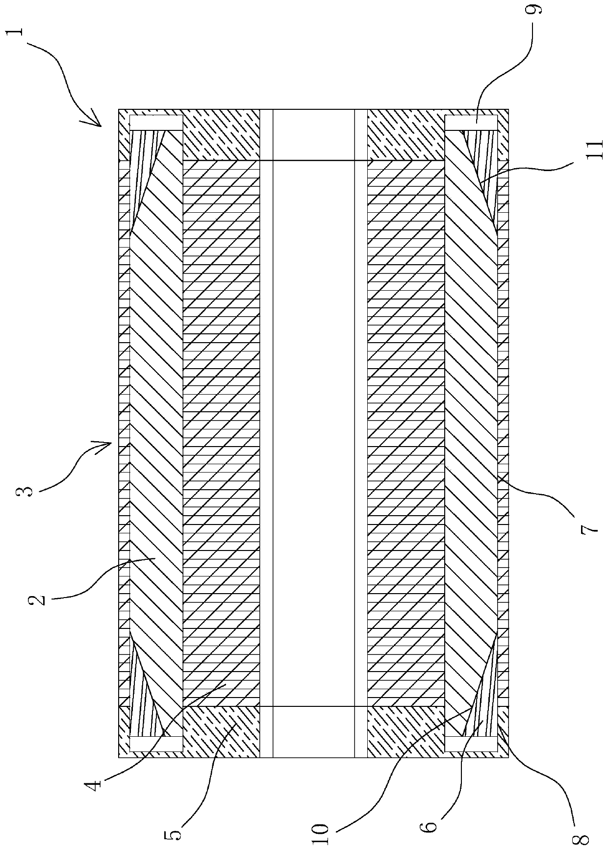
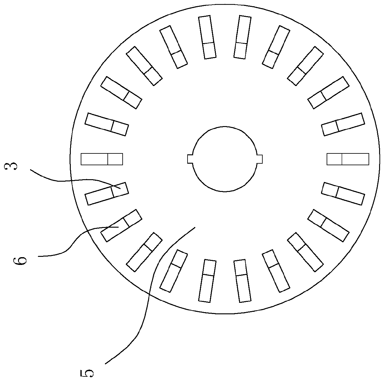
[0042] Such as figure 1 and figure 2 As shown in the figure, there is a transformation method for a motor that is never broken. The motor rotor 1 is composed of a rotor cage bar 2, an iron core 3 and an end ring 5. The rotor cage bar 2 is inserted into the iron core 3, and the two ends of the iron core 3 are respectively covered with One end ring 5, the rotor cage bar (2) is made of high-precision trapezoidal copper bars made of T2 copper, and the material of the end ring (5) is T2 copper forging.
[0043]The two ends of the rotor cage bar 2 pass through the iron core 3 and are welded with the end ring 5. There is also a tank 9 at the connection between the end ring 5 and the rotor cage bar 2. The rotor cage bar 2 passes through the iron core 3 and is inserted into the pool tank within 9,
[0044] The iron core 3 is formed by laminating several rotor silicon steel sheets 4 , and there are several high-precision guide bar slots 7 corresponding to the rotor cage bars 2 in the...
Embodiment 2
[0048] Such as figure 1 As shown, a method for transforming a motor that is never broken, including a motor rotor 1, includes the following steps:
[0049] Step 1: Order high-precision trapezoidal copper bars as the rotor cage bar 2 according to the design plan. The material is T2 copper. According to the design requirements and size of the motor rotor 1, redesign and customize two end rings 5 and iron core 3. The iron core 3 is made of A number of rotor silicon steel sheets 4 are stacked, and the iron core 3 is provided with a number of high-precision guide grooves 7 that are compatible with the rotor cage 2. The material of the end ring 5 is forged T2 copper, and according to the rotor cage 2 The size of the end, the pool groove 9 is gold-processed on the end ring 5;
[0050] In this embodiment, the rotor cage bar 2 made of trapezoidal copper bar structure can effectively prevent broken bars due to good heat dissipation, effective tensioning of the copper bar, and large s...
Embodiment 3
[0078] Wherein, the rotor silicon steel sheet 4 in the step 2 is made through the following steps:
[0079] Step a: Design the rotor silicon steel sheet 4 of the motor rotor 1, measure according to the required size and make tools such as pressure ring;
[0080] Step b: design the composite mold for the rotor silicon steel sheet 4 according to the drawing, and draw the construction drawing;
[0081] Step c: Make the mold of the rotor silicon steel sheet 4 according to the figure;
[0082] Step d: Punch rotor silicon steel sheet 4 on a large punching machine, the material is DW470-50 cold-rolled silicon steel sheet, and paint;
[0083] Step e: laminate several rotor silicon steel sheets 4 on a punching machine to form an iron core 3 .
PUM
| Property | Measurement | Unit |
|---|---|---|
| Diameter | aaaaa | aaaaa |
| Diameter | aaaaa | aaaaa |
| Diameter | aaaaa | aaaaa |
Abstract
Description
Claims
Application Information
 - R&D
- Intellectual Property
- Life Sciences
- Materials
- Tech Scout
- Unparalleled Data Quality
- Higher Quality Content
- 60% Fewer Hallucinations
Browse by: Latest US Patents, China's latest patents, Technical Efficacy Thesaurus, Application Domain, Technology Topic, Popular Technical Reports.
© 2025 PatSnap. All rights reserved.Legal|Privacy policy|Modern Slavery Act Transparency Statement|Sitemap|About US| Contact US: help@patsnap.com


