Composite girder for bridge construction

a composite girder and bridge technology, applied in bridges, arch-type bridges, building roofs, etc., can solve the problems of increased construction costs increased weight of steel box girders, weak steel box girders against vibration and droop, etc., to reduce manufacturing costs, reduce construction costs, and overcome compression and tension stress

Active Publication Date: 2013-05-02
SB ENG CO LTD
View PDF0 Cites 7 Cited by
  • Summary
  • Abstract
  • Description
  • Claims
  • Application Information

AI Technical Summary

Benefits of technology

The present invention is a composite girder for bridge construction that has an optimized structure to efficiently handle compression and tension stresses. The girder has a upwardly convexly curved shape and is integrally composed of a compression section, a steel web, and a steel tension section. The sectional strength of the girder is improved, allowing it to be mounted over a longer span. The composite girder reduces manufacturing costs and exhibits sufficient strength characteristics even with a small dead load. A stopper and a steel plate are formed to maintain strength characteristics, and a bracing is formed to resist torsion. The center of the girder formed long by filling the concrete in the compression section resists a certain compression stress in the bridge axis direction, minimizing the need for front-end connecting materials and reducing shearing stress. The flange placed on the boundary between the concrete of the compression section and the web is formed into the same arch structure, increasing resistance against the load in the direction perpendicular to the bridge axis. The composite girder achieves an optimized design for a bridge having torsional stress.

Problems solved by technology

On the other hand, since a large number of reinforcement materials should be used inside the steel box girder so as to improve strength, the construction costs of the steel box girder increase, and the weight of the steel box girder increases.
Further, the steel box girder is weak against vibration and droop due to characteristics of steel materials.
The PF beam girder is disadvantageous to be applied to curved bridges, and has the problem of a dead load.
On the other hand, the construction costs of the PF beam girder increase, and it is difficult to mend and reinforce the PF beam girder in the occurrence of cracks.
That is, the steel box girder and the tubular girder have large scale and large weight, and use expensive steel materials exhibiting strength characteristics as a tension member for a compression member at an upper portion of the girder, which is inefficient.
When considering characteristics of steel materials having weakness in terms of compression strength, an excessive number of steel reinforcement materials should be used to secure the compression strength of the upper portion of the girder, and the torsional strength is weak.
Therefore, the weight of steel is increased by 40% or more, and an increase in construction cost is caused.
Further, it is difficult to apply the steel box girder and the tubular girder as girders having a maximum long span of 70 m or more due to excessive weight of steel as compared with the strength of steel materials.
In the I-beam girder, the girder height (main girder height) should be increased to secure strength, and the structure of the I-beam girder may be unstable due to the weakness of torsional strength.
The I-beam girder is efficient because of its sectional characteristics, but it is difficult to apply the I-beam girder as a girder having a long span.
Therefore, the dead load of a structure increases, and economic efficiency is deteriorated due to the excessive use of construction materials.

Method used


Image

  • Composite girder for bridge construction
  • Composite girder for bridge construction
  • Composite girder for bridge construction

Examples


Embodiment Construction

[0040]A composite girder for bridge construction according to a preferred embodiment of the present invention will be described in detail with reference to the accompanying drawings.

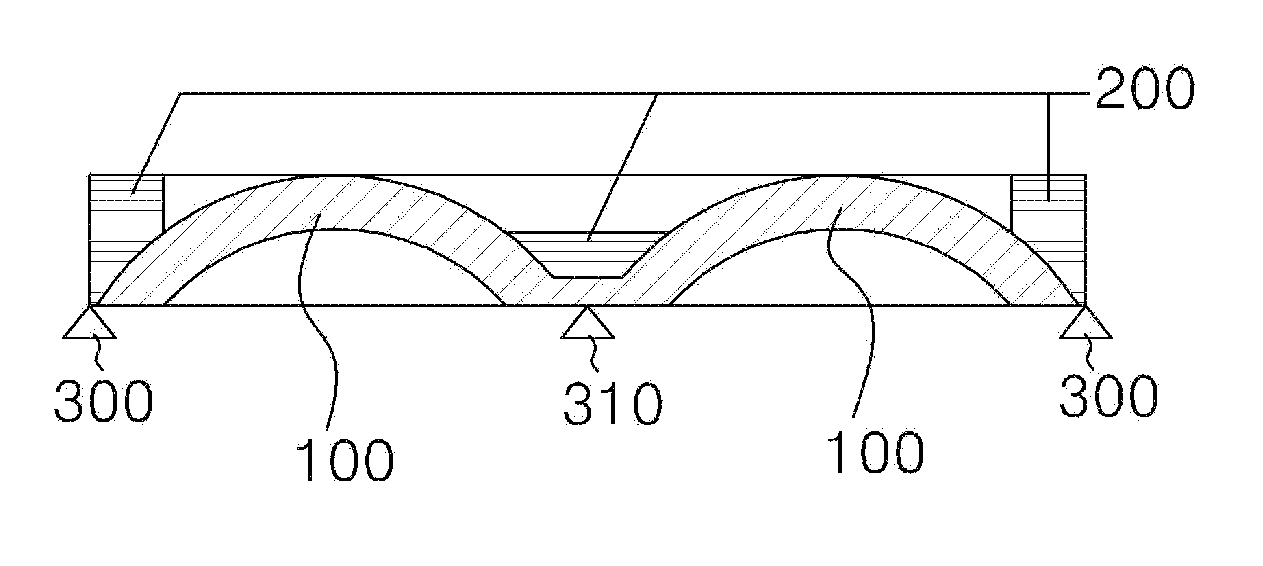
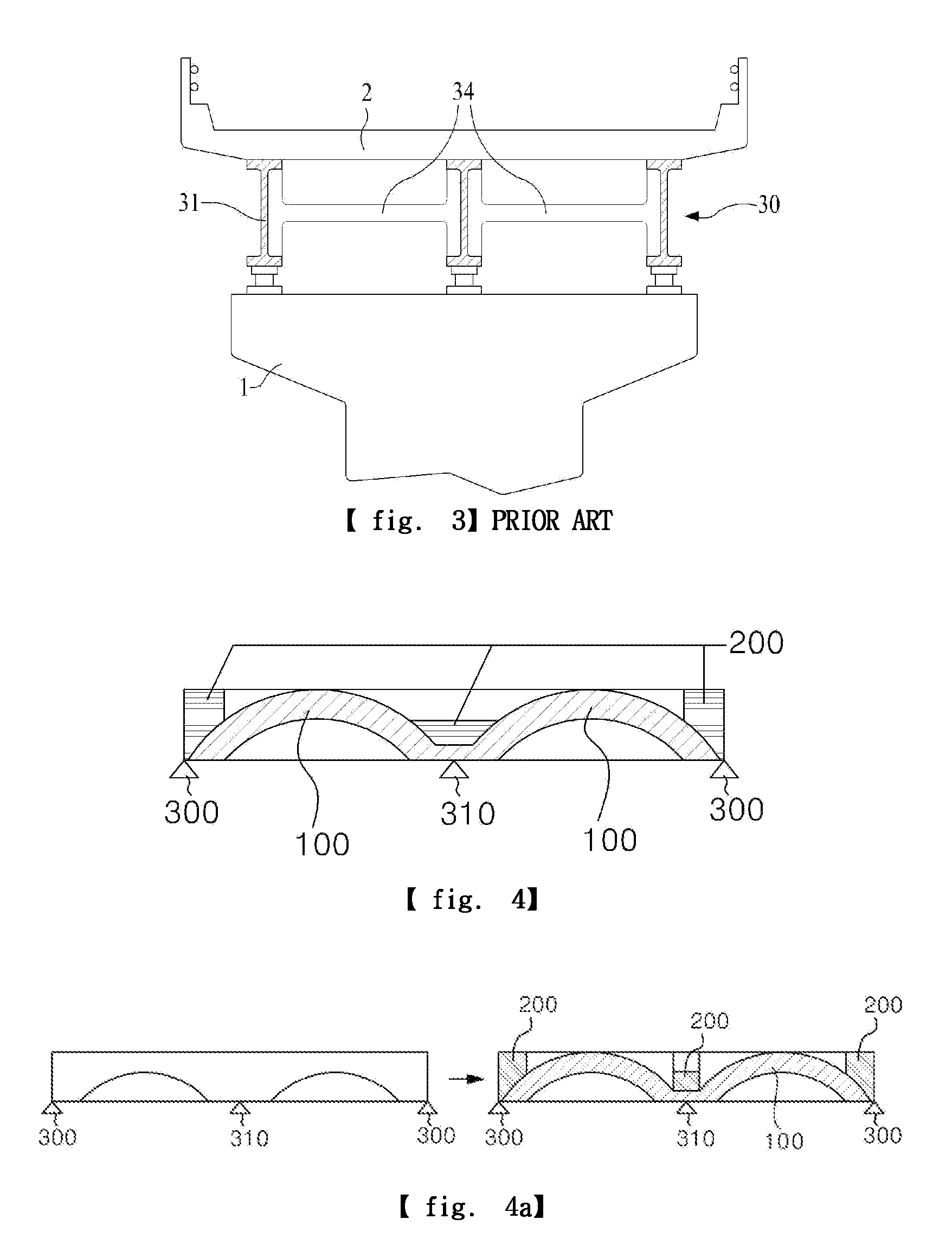
[0041]The present invention has a structure in which steel materials and concrete used in a bridge, a building or the like are integrally formed to increase resistance against warping, a tension section (lower flange) of the girder, which receives a tensioning force, uses steel materials so as to economically improve capability of resisting warping, and a compression section (upper flange) of the girder, which receives a compressing force, uses concrete having excellent compression strength as compared with its price.

[0042]The present invention provides specific structures of the girder. In the girder receiving a uniformly distributed a load, the compression section in which steel materials and concrete are integrally composed together is formed, so that it is possible to minimize shearing stress between...


PUM


Abstract

The present invention pertains to a composite girder for bridge construction. More preferably, a girder is formed in a rectangular shape that is horizontally long and opened at the top portion thereof, wherein the girder is convexly curved in the center so as to be formed in the shape of an arch. The girder has a compression section, a web and a tension section, which are integrally composed together; and is filled with concrete inside the girder so as to increase the sectional strength of the girder. Therefore, it is possible to reinforce a support that receives a great shearing stress even without the use of any rebar. Simultaneously, a stopper is formed on the inside surface of the compression section to prevent the separation of the steel materials and the concrete. Therefore, compared with the existing girders, the composite girder of the present invention may be mounted over a noticeably long span. In addition, it is possible to reduce manufacturing costs by minimizing the use of expensive steel reinforcement materials, exhibiting sufficient strength characteristics in spite of a small dead load.

Description

TECHNICAL FIELD[0001]The present invention pertains to a composite girder for bridge construction. More preferably, a girder is formed in a rectangular shape that is horizontally long and opened at the top portion thereof, wherein the girder is convexly curved in the center so as to be formed in the shape of an arch. The girder has a compression section, a web and a tension section, which are integrally composed together; and is filled with concrete inside the girder so as to increase the sectional strength of the girder. Therefore, it is possible to reinforce a support that receives a great shearing stress even without the use of any rebar. Simultaneously, a stopper is formed on the inside surface of the compression section to prevent the separation of the steel materials and the concrete. Therefore, compared with the existing girders, the composite girder of the present invention may be mounted over a noticeably long span. In addition, it is possible to reduce manufacturing costs ...

Claims


Application Information

Patent Timeline
IPC IPC(8): E01D2/00
CPCE01D2/00E04C3/293E04C3/46E01D2/04E01D2101/268E01D2/02
Inventor WON, YONG-SEOCK
Owner SB ENG CO LTD
Why Eureka
Try Eureka