Air humidifier with purification function
An air humidifier and functional technology, applied in the field of air humidifiers, can solve the problems of low humidification rate and difficult control of humidification effect, achieve low air flow rate, significant air purification effect, and increase humidification effect
- Summary
- Abstract
- Description
- Claims
- Application Information
AI Technical Summary
Problems solved by technology
Method used
Image
Examples
Embodiment 1
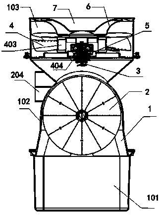
[0050] refer to figure 1 , Figure 12 As shown, one embodiment of the present invention is an air humidifier with purification function, comprising a housing 1, the lower part of the housing 1 is provided with a water tank 101, wherein the water tank 101 is an existing water tank, and the housing 1 and The water tank can be assembled or integrated.
[0051] The housing 1 is also equipped with an evaporating device 2 and a water diversion structure 3 , the evaporating device 2 is located above the water tank 101 , and the lowest level of the evaporating device 2 is higher than the highest liquid level in the water tank 101 .
[0052] Wherein, the evaporating device 2 is always above the water tank, so as to prevent the evaporating device 2 from being soaked by the liquid in the water tank, and prevent the evaporating device 2 from being greatly fluctuated in the humidification effect due to the influence of the water level.
[0053] The upper end of the housing 1 is provided ...
Embodiment 2
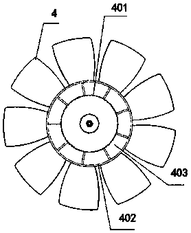
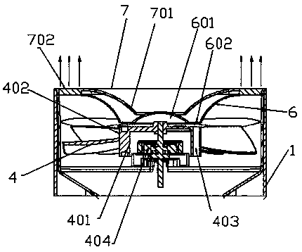
[0063] Based on the above examples, refer to figure 2 , image 3 As shown, in another embodiment of the present invention, in order to ensure that the humidification water can be replenished without stopping the machine, the above-mentioned fan assembly 4 includes an inner wall 401 and an outer wall 402, the above-mentioned inner wall 401 and the outer wall 402 are solidly integrated, and the above-mentioned inner wall 401 and the outer wall 402 A water injection channel 403 is set between them.
[0064] Wherein, the inner wall 401 and the outer wall 402 are reinforced by beams, so that the inner wall 401 and the outer wall 402 form an "H" shape, and there is a gap between two adjacent beams, and the gap forms a water injection channel 403 .
[0065] The fan blades of the fan assembly 4 are installed on the outer wall 402; the driving motor 404 is installed inside the inner wall 401, and the inner wall 401 isolates the contact of the driving motor 404 in the water flow area,...
Embodiment 3
[0078] Based on the above examples, refer to Figure 6 , Figure 7 As shown, another embodiment of the present invention is to disperse the water in the water tank 101 to the evaporation device 2 more easily; the above-mentioned water separation structure 3 is placed above the evaporation device 2 so that under the same water pressure, Enhanced spray effect by gravity.
[0079] The water diversion structure 3 includes an atomizing shower head 301 and a water diversion blade 302 . The water inlet end of the atomization shower head 301 is connected to a water pump, and water is supplied to the atomization shower head 301 of the water diversion structure 3 through the water pump.
[0080]At least one nozzle 303 is provided at the end of the atomizing shower head 301 , and the water flow is dispersed to one or more nozzles 303 through the atomizing shower head 301 , and water mist is formed through the nozzles 303 for spraying.
[0081] The above-mentioned water-dividing blade 3...
PUM
 Abstract
Description
Claims
Application Information
 - R&D
- Intellectual Property
- Life Sciences
- Materials
- Tech Scout
- Unparalleled Data Quality
- Higher Quality Content
- 60% Fewer Hallucinations
Browse by: Latest US Patents, China's latest patents, Technical Efficacy Thesaurus, Application Domain, Technology Topic, Popular Technical Reports.
© 2025 PatSnap. All rights reserved.Legal|Privacy policy|Modern Slavery Act Transparency Statement|Sitemap|About US| Contact US: help@patsnap.com


