Method And Apparatus For Controlling The Delivery Of Humidified Air

Inactive Publication Date: 2013-10-17
DEVILBISS HEALTHCARE
View PDF7 Cites 10 Cited by
  • Summary
  • Abstract
  • Description
  • Claims
  • Application Information

AI Technical Summary

Benefits of technology

The present invention is a method for using a CPAP machine to improve the humidification of the air being breathed by the user. The method addresses the problem of rain-out by cooling down the air during the exhalation phase of the breathing cycle and reducing the likelihood of rainout while also reducing power consumption. The method requires the user to fill the water reservoir less often, resulting in a significant reduction in water consumption and power consumption of the device.

Problems solved by technology

There are several problems existing with the current humidification devices for the CPAP machines.
The condensed water tends to accumulate in the hose and may even block certain portions of the hose, forcing the user to breath are through the accumulated water, creating a “gurgling” sound and interfering with pressure delivery to the patient.
However, this solution is undesirable in that it tends to increase the overall power consumption of the machine and cost of the air supply tube which is usually disposable and replaced at set intervals.
In addition to the rain-out problem, the heating of the water also increases the overall power consumption of the machine.

Method used


Image

  • Method And Apparatus For Controlling The Delivery Of Humidified Air
  • Method And Apparatus For Controlling The Delivery Of Humidified Air
  • Method And Apparatus For Controlling The Delivery Of Humidified Air

Examples


Embodiment Construction

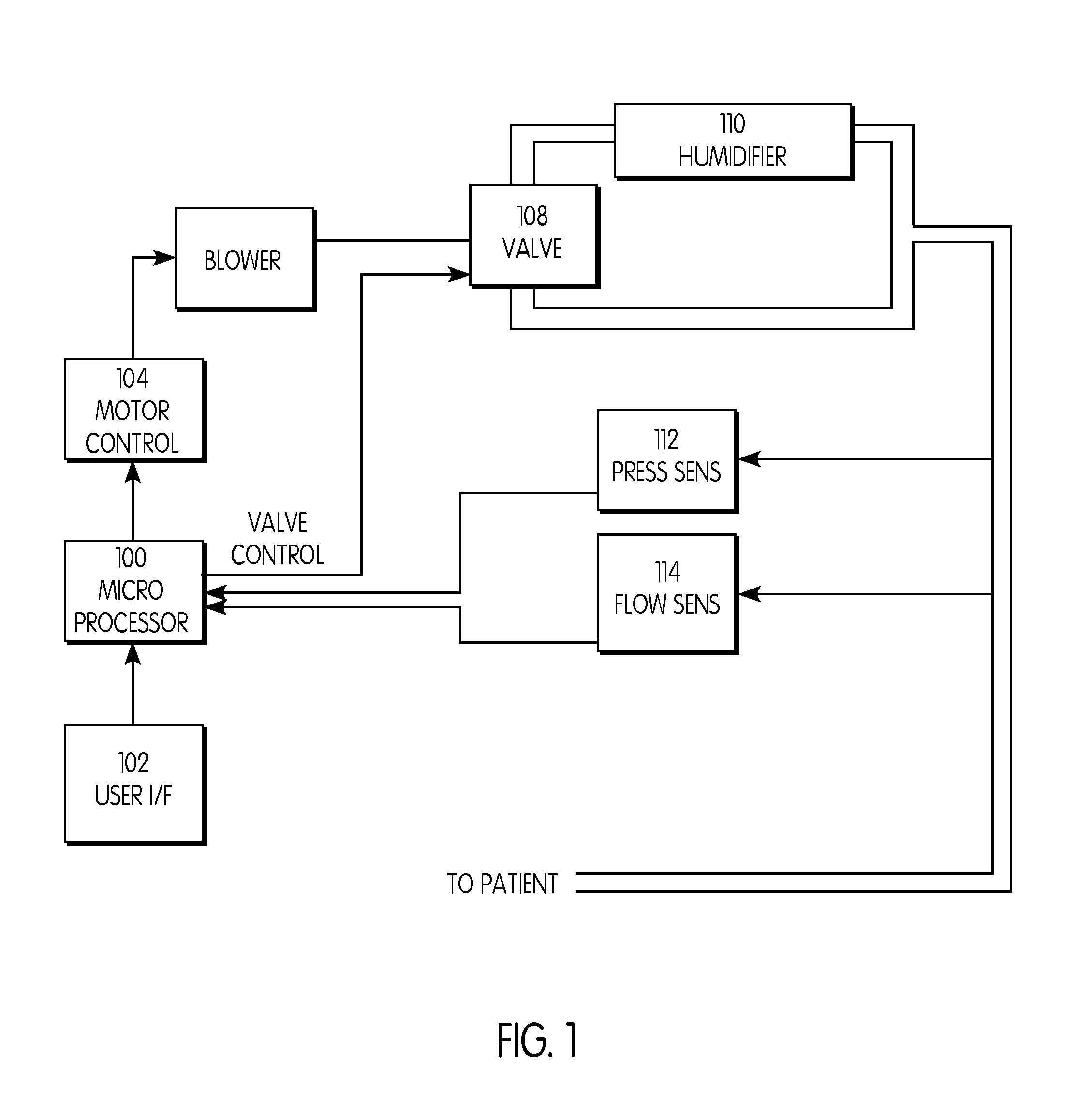
[0018]FIG. 1 shows a block diagram of a CPAP machine containing the improved humidifying apparatus of the present invention. The machine is controlled by microprocessor 100. Microprocessor 100 controls blower 106 through motor control 104 to control both the pressure and the airflow rate delivered to the patient. Pressure sensor in 112 and flow sensor 114 are utilized by microprocessor 100 to determine when the inhalation and exhalation phases of the breathing cycle occur. These sensors may be located anywhere between blower 106 and the patient. The user interface 102 is coupled to microprocessor 100 and allows use to set certain parameters of the machine, including the humidification level.

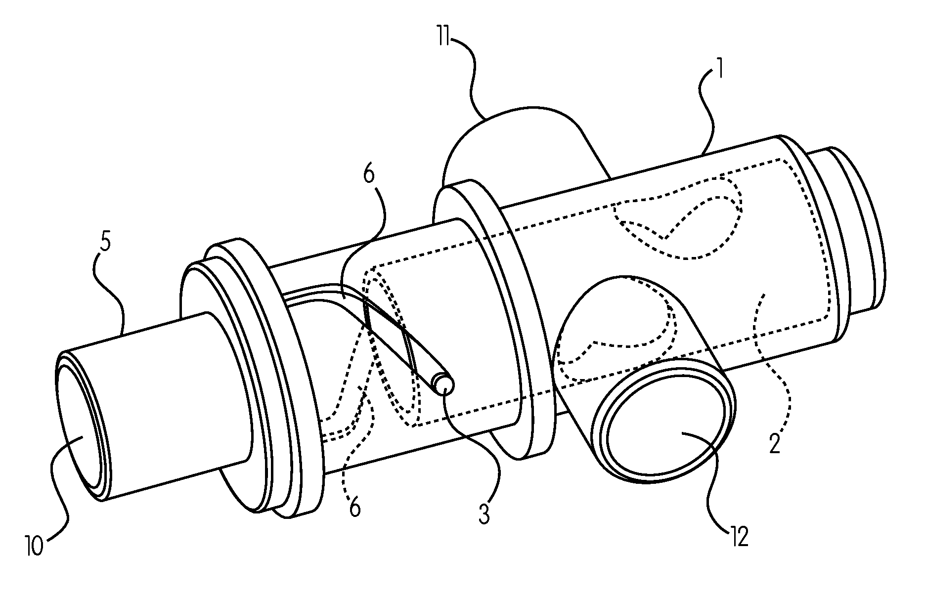
[0019]In a preferred embodiment of the invention, the microprocessor 100 also controls solenoid-enable valve 108 which can be in one of two states. In the first state, valve 108 allows airflow to pass from blower 106 through humidifier 110. In the second state, valve 108 diverts the airflow away ...


PUM


Abstract

An improved humidification method and apparatus for use with a CPAP type machine in which humidified air is delivered to the patient only during the inhalation phase and non-humidified air is delivered to the patient during the exhalation phase. The invention consists of a valve apparatus to switch from humidified air to non-humidified air and a method of determining when to switch the state of the valve.

Description

FIELD OF THE INVENTION[0001]This invention is related to the field of breathing gas delivery machines, such as continuous positive airway pressure (CPAP) or bi-level positive airway pressure (Bi-PAP) machines of the type typically used to treat patients suffering from breathing disorders, such as hypopnea or apnea, and, in particular, is related to the humidification apparatus and methods for such devices.BACKGROUND OF THE INVENTION[0002]Continuous Positive Airways Pressure (CPAP) machines are well known in the art for use in the treatment of a number of respiratory conditions, such as sleep apnea and hypopnea, by supplying a continuous positive pressure to a patient's airway while the patient sleeps.[0003]It is well known in the art that such machines be equipped with a humidification apparatus to humidify the air being delivered to the patient. This tends to increase the comfort of the patient and eliminates the “dry mouth” condition experienced by many users of the machines.[0004...

Claims


Application Information

Patent Timeline
IPC IPC(8): A61M16/16
CPCA61M16/0051A61M16/20A61M2016/0027A61M2016/0036A61M2205/50A61M16/202A61M16/16A61M39/223A61M2016/0024A61M2039/224A61M2039/226A61M16/0069A61M16/024
Inventor NEATROUR, JOEL DAVIDKNEPPER, MICHAEL
Owner DEVILBISS HEALTHCARE
Why Eureka
Try Eureka