
Two-phase-three-phase modulation mode switching circuit and device

A technology of three-phase modulation and switching circuits, which is applied in the direction of controlling generators, electromechanical brakes, and electromechanical transmissions. Solve the effect of excessive heat generation

Inactive Publication Date: 2019-09-27
GD MIDEA AIR-CONDITIONING EQUIP CO LTD
View PDF7 Cites 3 Cited by
  • Summary
  • Abstract
  • Description
  • Claims
  • Application Information

AI Technical Summary

Problems solved by technology

[0005] The main purpose of the present invention is to provide a two-phase-three-phase modulation switching circuit and equipment, aiming at solving the problem that the fan or compressor system in the prior art cannot solve the problem of low signal-to-noise ratio and three-phase modulation when the two-phase modulation scheme is applied to light load. The technical problem of high heat generation when the phase modulation scheme is applied to heavy loads

Method used


Image

  • Two-phase-three-phase modulation mode switching circuit and device
  • Two-phase-three-phase modulation mode switching circuit and device

Examples


Embodiment Construction

[0032] The following will clearly and completely describe the technical solutions in the embodiments of the present invention with reference to the accompanying drawings in the embodiments of the present invention. Obviously, the described embodiments are only part of the embodiments of the present invention, not all of them. Based on the embodiments of the present invention, all other embodiments obtained by persons of ordinary skill in the art without creative efforts fall within the protection scope of the present invention.

[0033] It should be noted that if there is a directional indication (such as up, down, left, right, front, back...) in the embodiment of the present invention, the directional indication is only used to explain the position in a certain posture (as shown in the accompanying drawing). If the specific posture changes, the directional indication will also change accordingly.

[0034] In addition, if there are descriptions involving "first", "second" and ...


PUM


Abstract

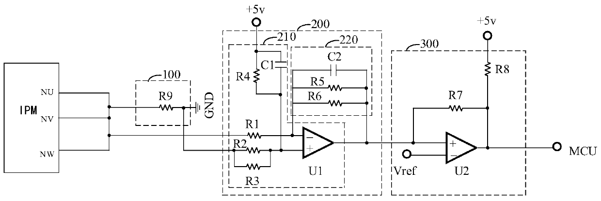
The invention discloses a two-phase-three-phase modulation mode switching circuit and device. The device is characterized in that a sampling circuit is connected with an intelligent power module, and the current of the intelligent power module is sampled to obtain a current signal; an operational amplifier circuit is respectively connected with a comparison circuit, the sampling circuit and the intelligent power module, after the current signal is converted into a voltage signal, the voltage signal is amplified to generate a first voltage; the comparison circuit is connected with a microcontroller, a first level is outputted to the microcontroller when the first voltage is greater than a reference voltage, a second level is outputted when the first voltage is less than the reference voltage, and the intelligent power module is controlled by the microcontroller for selecting a three-phase modulation mode or a two-phase modulation mode according to the first level or the second level. The device is advantaged in that the modulation modes are intelligently switched according to the load magnitude, three-phase modulation is utilized to improve the signal-to-noise ratio for light loads, a problem of faulty alarm of two-phase modulation during the light loads is solved, two-phase modulation is utilized to reduce heat during heavy loads, and a problem that the three-phase modulation heat is too high when the loads are heavy is solved.

Description

technical field [0001] The invention relates to the technical field of motor control, in particular to a two-phase-three-phase modulation switching circuit and equipment. Background technique [0002] The drive of the fan or compressor system usually adopts a modulation scheme based on space voltage vector, and the commonly used space voltage vector modulation scheme is a two-phase modulation scheme or a three-phase modulation scheme. [0003] In the two-phase modulation mode, one IGBT (Insulated Gate Bipolar Transistor, insulated gate bipolar transistor) is always on in each switching cycle, which can save 1 / 3 of the switching loss, and the efficiency is high, but narrow pulses may appear, and the sampling is easily affected. Interference, especially when the load is small and the current is small, because the signal is small and the noise is large, affects the waveform control, resulting in waveform distortion and false alarm failure. In the three-phase modulation mode, a...

Claims


Application Information

Patent Timeline
Patent Type & Authority Applications(China)
IPC IPC(8): H02P21/00
CPCH02P21/50
Inventor 杨建宁
Owner GD MIDEA AIR-CONDITIONING EQUIP CO LTD
Learn More