Oil-water separation component of oil separator

A technology of oil-water separation and oil separator, which is applied in the direction of grease/oily substance/suspton removal device, water/sewage treatment, chemical instruments and methods, etc., which can solve the problems of high cost and low cost of centrifugal separation, and achieve maintenance Oil scraping continuity, improved efficiency, good separation effect

Pending Publication Date: 2019-09-27
广东普施德泽环保股份有限公司
View PDF1 Cites 2 Cited by
  • Summary
  • Abstract
  • Description
  • Claims
  • Application Information

AI Technical Summary

Problems solved by technology

[0004] The main oil-water separation methods include gravity separation, centrifugal separation, electrical separation, adsorption separation, air flotation separation, etc. Among them, the cost of gravity separation and air flotation separation is low, while the cost of centrifugal separation and starch granules is relatively high

Method used


Image

  • Oil-water separation component of oil separator
  • Oil-water separation component of oil separator
  • Oil-water separation component of oil separator

Examples


Embodiment 1

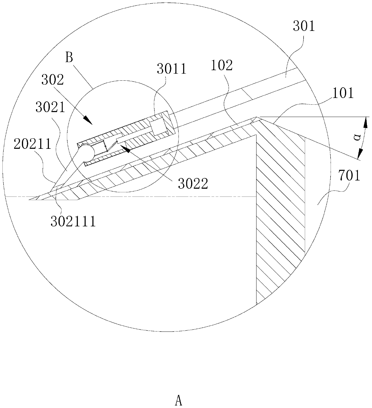
[0046] refer to figure 1 as well as figure 2 , this embodiment discloses an oil-water separation assembly of an oil separator, including an oil attachment plate 1 , a pneumatic conveying assembly 2 and an oil scraping assembly 3 .

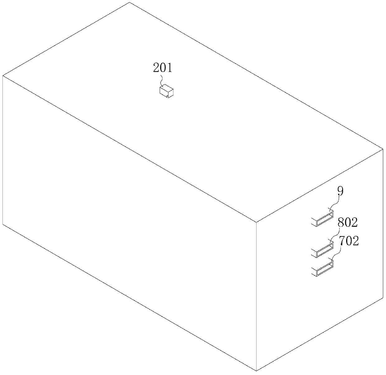
[0047] refer to figure 2 , in this embodiment, a separator 4 is arranged in the oil separator, and the separator 4 divides the space inside the oil separator into a solid-liquid separation chamber 5, an air bubble generation chamber 6, an oil-water separation chamber 7, and a drainage chamber 8. The separation chamber 5 is provided with a filter screen 501 for filtering solid impurities and realizing solid-liquid separation;

[0048] A bubble generator 601 is arranged in the bubble generating chamber 6, and an oil-water separation assembly is arranged in the oil-water separation chamber 7. In this embodiment, the bubble generator 601 is a commonly used microbubble generator 601 on the market;

[0049] The oil-water separation chamber 7 is prov...

Embodiment 2

[0074] refer to Figure 5 as well as Image 6 , this embodiment discloses another oil-water separation assembly for an oil separator. Based on Embodiment 1, the difference between this embodiment and Embodiment 1 is that an oil-water separation membrane 103 is also provided on the oil attachment plate 1, and the oil-water separation membrane 103 Laid on the upper surface of the oil attachment plate 1 and located on the lower surface of the oil-absorbing sponge layer 102, the oil attachment plate 1 is provided with a number of water filter holes 104, and the oil attachment plate 1 is provided with a return water tank 105 communicating with the water filter holes 104. The water tank 105 communicates with the lower surface of the oil-attached plate 1, so that when the air flow blows the oil layer to the oil-attached plate 1, the water layer following the lower layer passes through the oil-water separation membrane 103, the water filter hole 104, and the water return tank 105, and...

Embodiment 3

[0076] This embodiment discloses another oil-water separation assembly for an oil separator. Based on the above-mentioned embodiment, the difference between this embodiment and the above-mentioned embodiment is that the turning drive part is a servo drive motor, and the servo drive motor is arranged in the mounting seat, and The drive end of the servo drive motor is fixed to the arc portion of the oil scraper.


PUM

PropertyMeasurementUnit
thicknessaaaaaaaaaa
thicknessaaaaaaaaaa

Abstract

The invention discloses an oil-water separation component of an oil separator. The oil-water separation component comprises an oil attaching plate, a pneumatic conveying component and an oil scraping component, wherein an oil suction sponge layer is arranged on the surface of the oil attaching plate, the pneumatic conveying component comprises a gas supply device and a gas outlet pipe, the gas outlet pipe is connected with the gas supply device, a gas outlet of the gas outlet pipe is arranged toward a liquid surface and blows an oil layer on the liquid surface to the oil attaching plate, the oil scraping assembly comprises a telescopic driving member and an oil scraping portion, and the telescopic driving member drives the scraping portion to reciprocate along the surface of the oil attaching plate and to scrape the oil layer on the oil attaching plate into an oil collecting tank. By pneumatic conveying, during liquid conveying, disturbance to liquid in the oil separator is reduced, and the liquid is maintained in a layered state to be conveyed to the oil attaching plate, so that the oil layer is attached to the oil attaching plate, and then, the oil is scraped into the oil collecting tank by the oil scraping assembly to complete oil-water separation; the separation effect is good, water mixed in the separated oil is reduced, and the trouble of needing further oil-water separation is reduced.

Description

technical field [0001] The invention relates to the field of sewage treatment, in particular to an oil-water separation component of an oil trap. Background technique [0002] The so-called oil separator is a special equipment for separating impurities, oil and water in the oily wastewater of catering. As long as the sources of catering wastewater include hotels, hotels, canteens, etc., according to incomplete statistics, the discharge of catering wastewater accounts for about 3% of the urban domestic sewage discharge, but the BOD5 (biochemical oxygen demand for five days) and CODcr ( The content of dichromate oxygen demand) accounts for about 1 / 3 of the total load. It can be seen that catering wastewater is a high-concentration pollution source and one of the main causes of water pollution around cities. [0003] At present, oil-water separation is mainly based on the density or chemical properties of water and oil, using the principle of gravity sedimentation or other phy...

Claims


Application Information

Patent Timeline
Patent Type & Authority Applications(China)
IPC IPC(8): C02F9/02
CPCC02F1/001C02F1/24C02F1/40C02F9/00C02F2201/002C02F2303/14
Inventor 王鑫琦
Owner 广东普施德泽环保股份有限公司
Why Eureka
Try Eureka