
Combined wing electrodynamic unmanned aerial vehicle used for reservoir area cruising and capable of taking off and landing vertically

A vertical take-off and landing, electric power technology, applied in the direction of rotorcraft, unmanned aircraft, fuselage, etc., can solve the problems of waste time, waste power, low efficiency, etc., and achieve the advantages of simple operation, low cost, and reduced energy consumption Effect

Pending Publication Date: 2019-09-27
王颖 +1
View PDF0 Cites 2 Cited by
  • Summary
  • Abstract
  • Description
  • Claims
  • Application Information

AI Technical Summary

Problems solved by technology

At present, the regular inspection of reservoir divisions is mainly done manually, which is a waste of time and energy, and the efficiency is still very low

Method used


Image

  • Combined wing electrodynamic unmanned aerial vehicle used for reservoir area cruising and capable of taking off and landing vertically
  • Combined wing electrodynamic unmanned aerial vehicle used for reservoir area cruising and capable of taking off and landing vertically
  • Combined wing electrodynamic unmanned aerial vehicle used for reservoir area cruising and capable of taking off and landing vertically

Examples


Embodiment 1

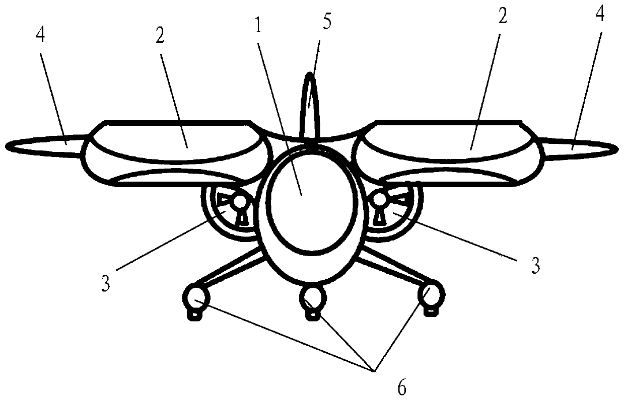
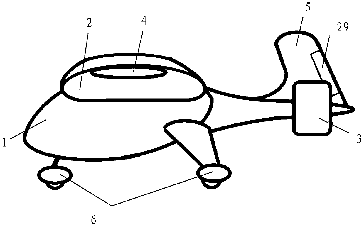
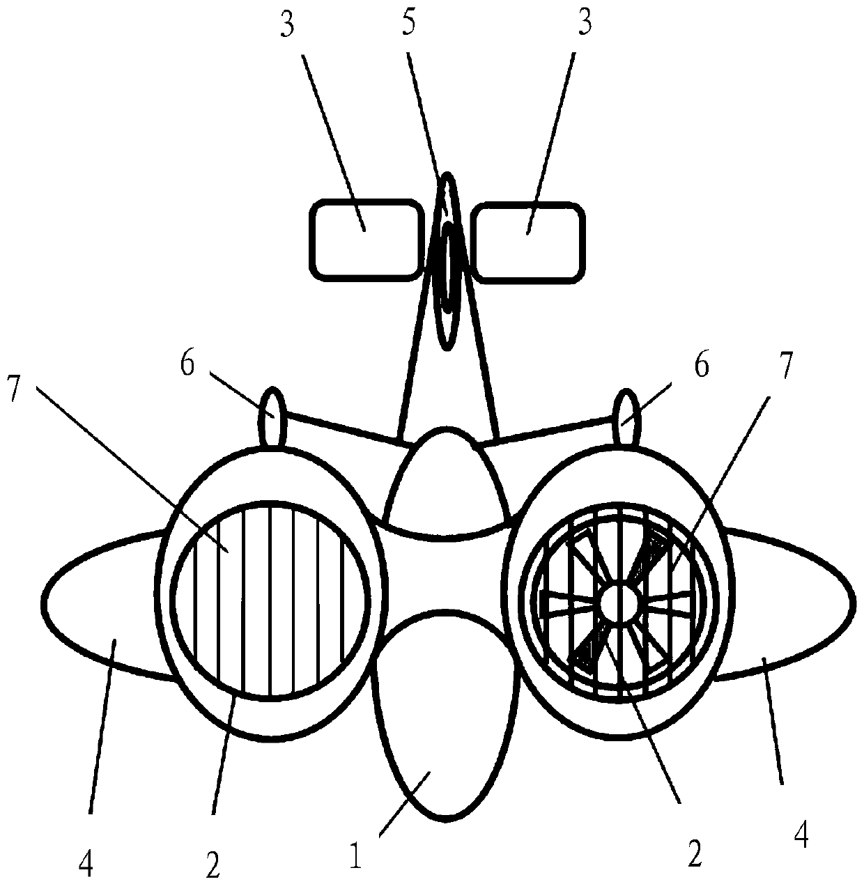
[0048] Embodiment one (wing is a straight round head shape wing, and empennage is a single vertical empennage)

[0049] Such as Figure 1A , Figure 1B and Figure 1C Shown, the present invention comprises fuselage 1, wing, empennage, landing gear, ducted type propulsion fan 3, flight control system and electric power source system, adopt vertical and horizontal power, ducted type propulsion fan 3 design separately.

[0050] The fuselage 1 is respectively equipped with a cockpit, a carrying compartment and a battery compartment. The cockpit and the carrying compartment are arranged in front of and behind the flight control system. It can be configured and installed according to different application requirements; the electric power source system is installed in the battery compartment, and the battery compartment is arranged at the rear bottom or the bottom of the middle rear part of the fuselage 1, and the flight control system and the electric power source system are respec...

Embodiment 2

[0079] Embodiment two (wing is the swept-back delta wing that folds down on the wingtip, no empennage)

[0080] Such as Figure 2A , Figure 2B and Figure 2C As shown, the present invention includes fuselage 1, wing, landing gear, ducted propulsion fan 3, flight control system and electric power source system, adopts vertical and horizontal power, and ducted propulsion fan 3 is separately designed. The arrangement in the fuselage 1 is the same as that in the first embodiment.

[0081] The wing of the present embodiment is the swept-back delta wing 8 with the tip of the wing folded down, that is, the wing is a swept wing with a triangular plane shape, which is inclined upward from the root of the wing to the tip of the wing, and folded downward at the tip of the wing; The wingtips on the side are folded down and the swept-back delta wing 8 is symmetrically arranged on the left and right sides of the fuselage 1 with the longitudinal central axis of the fuselage 1, and the wi...

Embodiment 3

[0086] Embodiment three (wing is the swept-back delta wing 9, and empennage is single vertical empennage 5)

[0087] Such as Figure 3A , Figure 3B and Figure 3C As shown, the present invention includes fuselage 1, wing, empennage, lift body 26, landing gear, ducted propulsion fan 3, flight control system and electric power source system, adopts vertical and horizontal power, ducted propulsion fan 3 Design separately. The arrangement in the fuselage 1 is the same as that in the first embodiment.

[0088] Two lifting bodies 26 are horizontally and symmetrically arranged on the left and right sides of the fuselage 1, and the two lifting bodies 26 have the same shape and are both streamlined. , the outer side is fixedly connected with wings; the wing of the present embodiment is a swept-back delta wing 9 (that is, the wing is a swept-back wing, and the planar shape is a triangle), and the swept-back delta wing 9 on the lifting body 26 of both sides is based on the machine. ...


PUM

PropertyMeasurementUnit
tensile strengthaaaaaaaaaa
elastic modulusaaaaaaaaaa
tensile strengthaaaaaaaaaa

Abstract

The invention relates to a combined wing electrodynamic unmanned aerial vehicle used for reservoir area cruising and capable of taking off and landing vertically. The combined wing electrodynamic unmanned aerial vehicle comprises an unmanned aerial vehicle body, ducted lift rotor wings, ducted propelling fans, wings, a tail wing, a landing gear, a flight control system and an electrodynamic source system; the number of the ducted lift rotor wings is an even number which is larger than or equal to 2, every two symmetrical rotor wings are reverse in rotation direction, and the ducted lift rotor wings are arranged on or embedded in the left side and the right side of the unmanned aerial vehicle body in a horizontally symmetrical mode or a mirror symmetry mode; the number of the ducted propelling fans is an even number which is larger than or equal to 2, every two symmetrical fans are reverse in rotation direction, and the fans are transversely and alternatively arranged at the tail of the unmanned aerial vehicle body in a horizontal symmetrical mode. The combined wing electrodynamic unmanned aerial vehicle can take off and land through any flat runway (or road) with a corresponding space, can take off in the vertical direction on any ground having a corresponding space, and can also conduct hovering, is suitable for low-altitude flight, and has the characteristics of being high in adaptability, safe, economical, environmentally friendly, convenient to control and the like.

Description

technical field [0001] The invention relates to reservoir cruising equipment, in particular to a compound-wing electric powered unmanned aerial vehicle capable of vertical take-off and landing for reservoir area cruising. Background technique [0002] Reservoir areas need to be regularly inspected, such as river channel inspections, to check whether there is fish stealing in the reservoir, to check whether there are pollution sources (such as paper mills, smelters) in the reservoir area of ​​the upstream reservoir, and whether they are secretly discharged into the reservoir area Pollutants, check whether the upstream residents of the reservoir area are farming land and whether they have encroached on the land used in the reservoir area. At present, the regular patrol inspection of the reservoir zoning is mainly done manually, which is a waste of time and energy, and the efficiency is still very low. Contents of the invention [0003] In order to solve the above-mentioned ...

Claims


Application Information

Patent Timeline
Patent Type & Authority Applications(China)
IPC IPC(8): B64C1/06B64C27/28B64D27/24C09D107/00C09D109/00C09D7/61C09D7/62C09D7/63
CPCB64C1/068B64C27/28B64D27/24C09D107/00C09D7/61C09D7/62C09D7/63C08K2003/221C08K2003/2296C08K2003/2213C08L2201/08B64U10/00B64U50/19C08L9/00C08K13/06C08K9/06C08K3/22C08K3/36C08K3/34C08K5/09C08K5/47Y02T50/60
Inventor 王颖郭亮高峰
Owner 王颖
Learn More