
A Combined Spiral Reinforced Bone Anchor

A bone anchor and combined technology, applied in the directions of nails, U-shaped nails, surgical fixation nails, etc., can solve the problems of loosening, increase the difficulty of operation, weak anchor holding force, etc., to prevent loosening and slippage, and easy to make Convenience and the effect of promoting tendon and bone healing

Active Publication Date: 2022-05-06
石岩
View PDF11 Cites 0 Cited by
  • Summary
  • Abstract
  • Description
  • Claims
  • Application Information

AI Technical Summary

Problems solved by technology

However, the anchors in the prior art often encounter the following problems when they are used: 1. The holding force of the anchor is weak, and the anchor is often loosened or pulled out during or after the operation, resulting in failure of fixation. Cases of osteopenia or osteoporosis; 2. When the anchors are implanted in the bone, a certain distance between the anchors needs to be kept, otherwise the fixation strength will be affected, which limits the number of anchors implanted; 3. Once the anchors occur After loosening and pulling out, it is difficult to re-implant in situ, and the anchor needs to be re-implanted at a position far away from the original hole, which not only increases the difficulty of operation, but also seriously affects the reliability of intraoperative fixation; 4. Anchor fixation more bone damage
The above-mentioned patent application designs the bone screw as a helical structure, which to a certain extent solves the shortcomings of the traditional thread structure or protruding wing-shaped anchors such as the limited implantation position and quantity, and more bone damage. However, the bone screw The implanted part is a spiral filament-like structure, and its anchoring strength is low. The end of the bone screw close to the bone plate or suture has a large degree of freedom of deformation, which affects its anchoring strength; and the holding force of the implanted part is from outward to outward. The inside changes. Generally speaking, the holding force on the inside is greater, while the holding force on the outside is reduced due to the low local strength of the helical filament structure. Therefore, it is easy to loosen the bone on the outside during use, especially for For patients with osteopenia or osteoporosis, the anchoring strength needs to be further improved

Method used


Image

  • A Combined Spiral Reinforced Bone Anchor
  • A Combined Spiral Reinforced Bone Anchor
  • A Combined Spiral Reinforced Bone Anchor

Examples


Embodiment 1

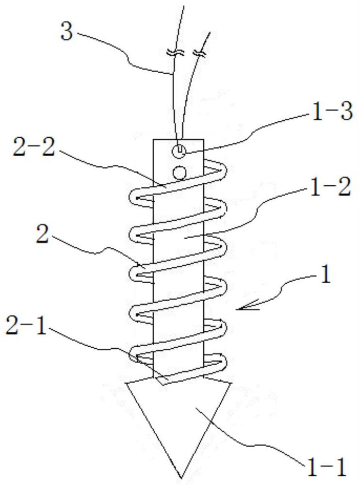
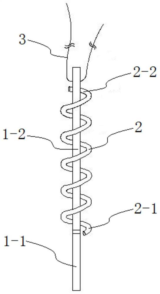
[0032] combine figure 1 and figure 2 As shown, a combined helical reinforced bone anchor in this embodiment includes two parts: an anchor 1 and a helical nail 2, wherein the anchor 1 includes an anchor head 1-1 and an anchor body 1-2, The anchor head 1-1 is integrated at the front end of the anchor body 1-2, the anchor head 1-1 and the anchor body 1-2 are integrally formed, and the width of the anchor head 1-1 is larger than that of the anchor body The width of 1-2 forms a stepped structure at the connection position between the anchor head 1-1 and the anchor body 1-2, and the tail of the anchor body 1-2 is provided with a thread hole 1-3 for threading the suture 3. The anchor 1 preferably adopts a flat structure, and the anchor head 1-1 is sharp, so that the anchor 1 can be driven into the pre-drilled bone hole, and the anchor 1 is easy and convenient to manufacture.

[0033]The helical screw 2 includes a helical main body, the front of the helical main body has a sharp na...

Embodiment 2

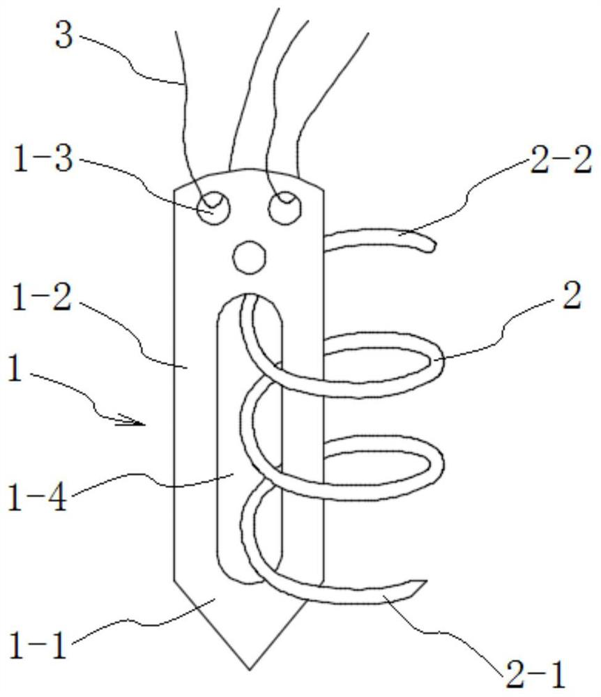
[0037] combine image 3 As shown, a combined spiral-reinforced bone anchor of this embodiment has a principle similar to that of Embodiment 1, and includes two parts, an anchor 1 and a helical nail 2, wherein the anchor 1 includes an anchor head 1- 1 and the anchor body 1-2, the anchor head 1-1 is integrally arranged at the front end of the anchor body 1-2, the anchor head 1-1 is integrally formed with the anchor body 1-2, the anchor body 1- The tail part of 2 is provided with the wire hole 1-3 that is convenient for suture 3 to penetrate, and the nail piercing hole 1-4 that extends along the length direction is provided on the anchor main body 1-2, and this nail piercing hole 1-4 is preferably waist-shaped hole structure. The anchor 1 preferably adopts a flat structure, and the anchor head 1-1 is sharp, so that the anchor 1 can be driven into the pre-drilled bone hole, and the anchor 1 is easy and convenient to manufacture.

[0038] The helical screw 2 includes a helical ma...


PUM


Abstract

The invention discloses a combined spiral reinforced bone anchor, which belongs to the field of medical instruments. The combined spiral-reinforced bone anchor of the present invention includes two parts: an anchor and a helical screw. The anchor includes an anchor head and an anchor main body. The helical screw includes a helical main body. head with a tail for helical screw rotation implantation at the rear. The present invention organically combines the anchor and the helix. When using the anchor, the anchor is driven in first, and then the helix is ​​screwed in. The helix is ​​used to provide the holding force of the anchor in the bone. It can effectively disperse stress and cause little damage to bone; in addition, the distance and quantity of anchor implantation are limited, and the anchor implantation density can be higher, which is especially suitable for tendon suture fixation in patients with osteoporosis ; and if the anchor is loose, it can be reimplanted in situ by replacing the screw with a larger diameter, and the operation is simpler and more flexible.

Description

technical field [0001] The invention relates to a medical bone anchor, more specifically to a combined helical reinforced bone anchor, in particular to a minimally invasive suture anchor for repairing tendon damage. Background technique [0002] Complete or partial separation of ligaments, tendons, or other soft tissues from the bone to which they are attached is a relatively common injury. Partial separations can usually be treated conservatively with satisfactory results, but complete separations require surgical treatment to complete the soft tissue repositioning of the bone. attached. A suture anchor is a miniature device used to connect soft tissues such as tendons and ligaments to bones in surgical operations. It can fix the damaged tendon stump to bone tissue to restore the normal structure and joint function of the tendon. Through tendon-bone healing final fixed purpose. [0003] The process of tendon-bone healing requires a certain contact area and firm contact st...

Claims


Application Information

Patent Timeline
Patent Type & Authority Patents(China)
IPC IPC(8): A61B17/064A61B17/04
CPCA61B17/0642A61B17/0401A61B2017/0408A61B2017/044A61B2017/0464
Inventor 石玥
Owner 石岩
Learn More