
Fuel cell stack with central manifold

A fuel cell stack and manifold technology, applied in fuel cells, fuel cell additives, circuits, etc., can solve problems such as increased costs, and achieve the effects of saving production costs, saving space, and reducing volume

Pending Publication Date: 2019-09-24
苏州奥加华新能源有限公司
View PDF0 Cites 4 Cited by
  • Summary
  • Abstract
  • Description
  • Claims
  • Application Information

AI Technical Summary

Problems solved by technology

In addition, changes in battery hardware may require changes to the BOP and fuel cell stack installation interface, and the increase in size and specification will undoubtedly increase the specification, resulting in higher costs

Method used


Image

  • Fuel cell stack with central manifold
  • Fuel cell stack with central manifold
  • Fuel cell stack with central manifold

Examples


Embodiment

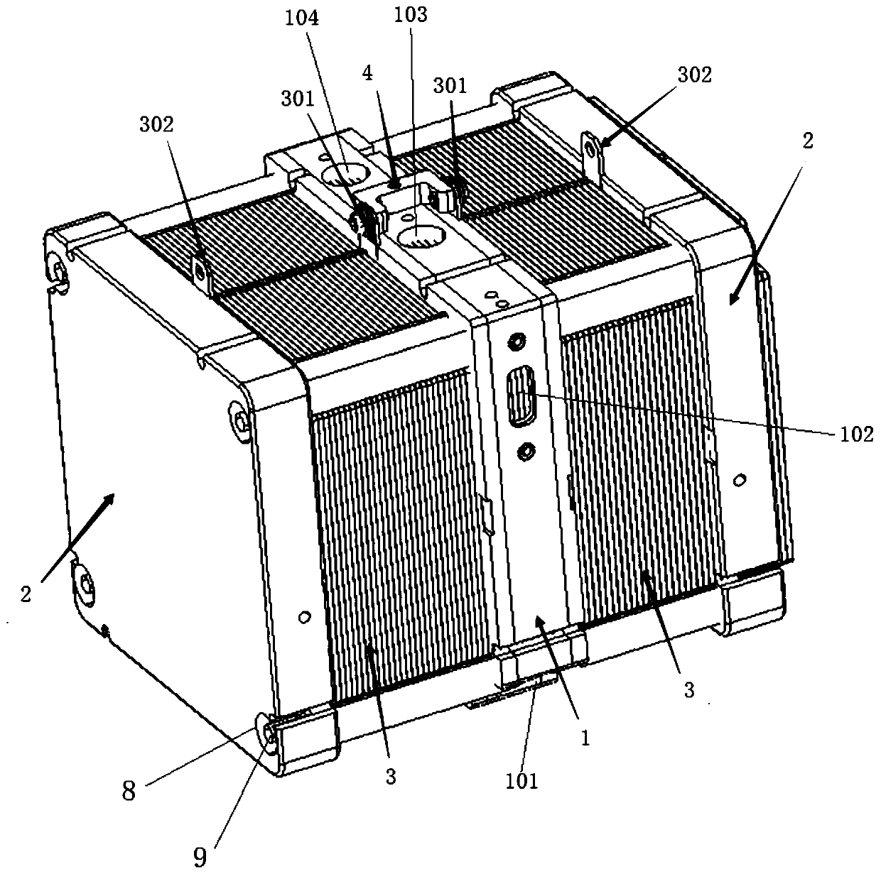
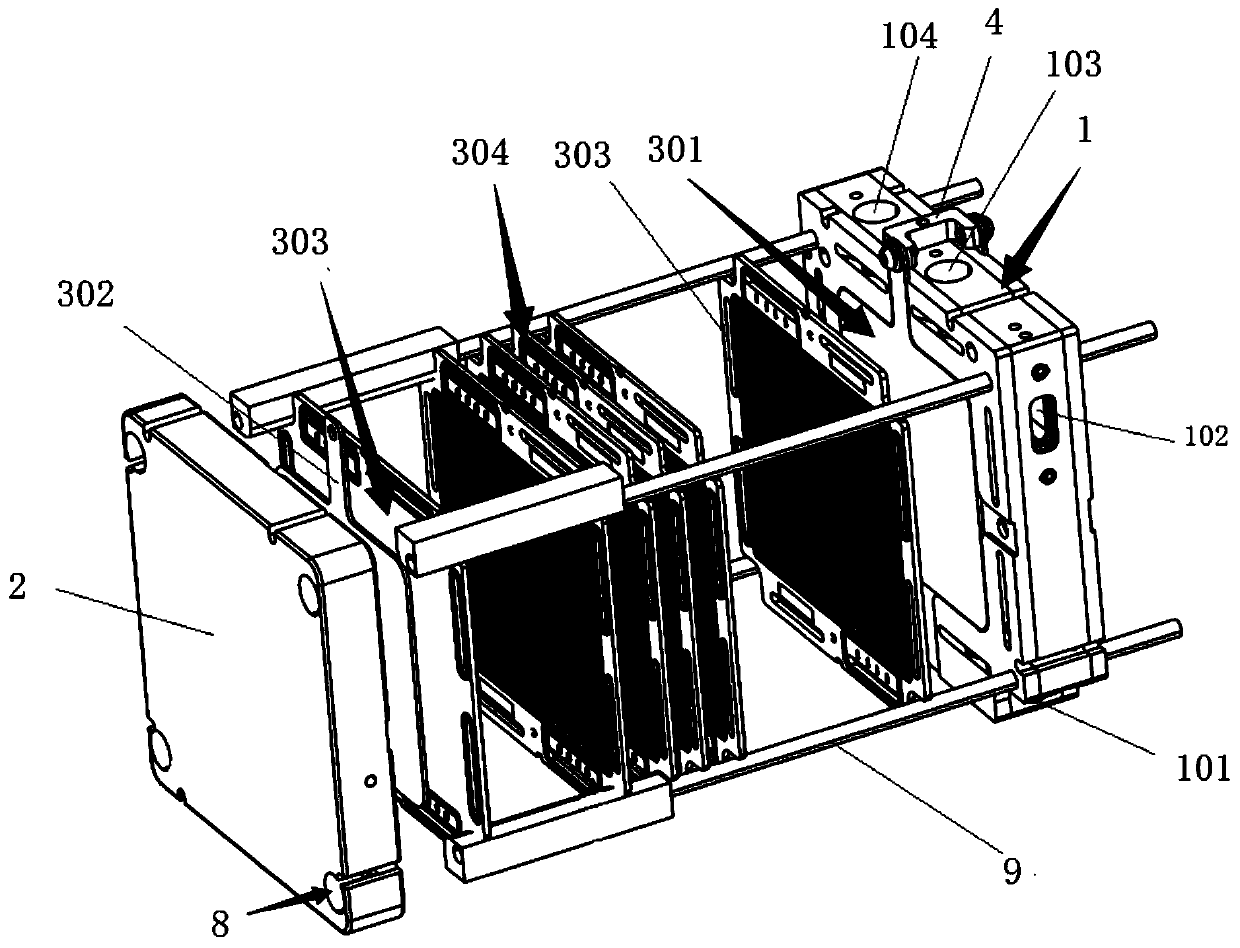
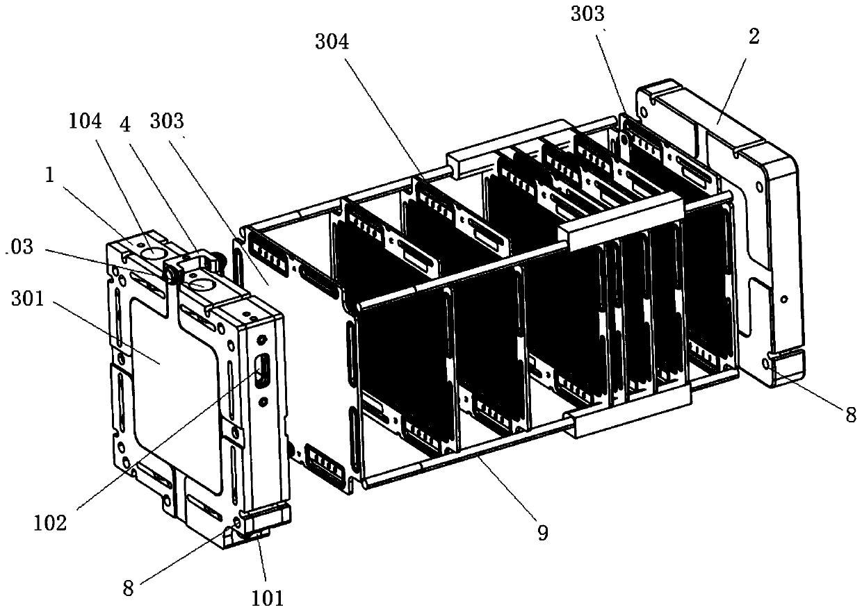
[0049] Embodiment: combine below Figure 1~Figure 8 A specific implementation of the fuel cell stack with a central manifold provided by the present invention is described in detail as follows:

[0050] first as figure 1 As shown, it has a central manifold 1, end plates 2 arranged on both sides of the central manifold 1, and a fuel cell stack 3 fixed between the central manifold 1 and each end plate 2, and the two fuel cell stacks 3 share The central manifold 1 is connected in series; in this embodiment, the power of the two fuel cell stacks 3 on both sides is 500W, and the stack power after series connection is 1000W.

[0051] further combined figure 2 and image 3 As shown, the fuel cell stacks 3 on both sides are structurally symmetrical, and are composed of a connection collector plate 301 fixed on the central manifold 1, an output collector fixed on the end plate 2 with opposite polarity to the connection collector plate 301 The electrical plate 302 and a plurality o...


PUM


Abstract

The invention discloses a fuel cell stack with a central manifold. The fuel cell stack is characterized by comprising two fuel cell stacks which are fixed between the central manifold and two side end plates, share the central manifold and are connected in series; each fuel cell stack includes a plurality of single cells which are arranged in a laminated manner, the central manifold is internally provided with an anode distribution cavity and a cathode distribution cavity which are respectively used for simultaneously supply anode reaction fuel and cathode reaction fuel to the anode and the cathode of the single cells in the fuel cell stacks on the two sides, the central manifold is further provided with an anode confluence cavity and a cathode confluence cavity which are respectively used for simultaneously collecting anode reaction substances and cathode reaction substances from the anode and the cathode of the single cells in the fuel cell stacks on the two sides; and the central manifold is provided with an anode inlet interface, a cathode inlet interface, an anode outlet interface and a cathode outlet interface which are respectively communicated with the cavities. The fuel cell stack with the central manifold allows the series connection of small fuel cell stacks through sharing the central manifold, thereby establishing a cell stack with a large size and higher power in the compact space, and saving the space and the production cost.

Description

technical field [0001] The present invention relates to a fuel cell stack with a central manifold. Background technique [0002] A fuel cell (FC), like a normal battery, provides direct current through two electrochemical reactions. These reactions take place at electrodes with a continuous supply of reactants. For example, in a direct methanol fuel cell (DMFC), the negative electrode (anode) is maintained by supplying fuel such as methanol, while the positive electrode (cathode) is maintained by supplying oxygen or air. When an electric current is supplied, methanol is electrochemically oxidized at the anode electrocatalyst to generate electrons, which are transported through an external circuit to the cathode electrocatalyst, where they are consumed in a reduction reaction together with oxygen. This circuit is maintained within the battery by proton conduction in the electrolyte. [0003] A fuel cell stack usually consists of a series of battery cells. Each battery cel...

Claims


Application Information

Patent Timeline
IPC IPC(8): H01M8/0258H01M8/0267H01M8/04082H01M8/04089H01M8/2484
CPCH01M8/04201H01M8/04089H01M8/0258H01M8/0267H01M8/2484Y02P70/50Y02E60/50
Inventor 祝向齐刘绍华
Owner 苏州奥加华新能源有限公司
Learn More