
Probe type high-flux spark plasma sintering equipment

A technology of discharge plasma and sintering equipment, applied in the field of material science, can solve the problems of low efficiency, time-consuming energy consumption, high energy consumption, etc., and achieve the effect of speeding up the research process and improving the preparation efficiency

Inactive Publication Date: 2019-09-24
INST OF PHYSICS - CHINESE ACAD OF SCI
View PDF5 Cites 1 Cited by
  • Summary
  • Abstract
  • Description
  • Claims
  • Application Information

AI Technical Summary

Problems solved by technology

[0004] Since the vast majority of SPS equipment is designed for large-scale samples and large-scale industrial production, it cannot realize the synthesis and sintering of large-scale samples at one time, and the sample preparation process is time-consuming and energy-consuming. Efficient and rapid material screening and optimization expected by the work are contradictory
However, with the rapid development of various material characterization and performance measurement technologies in recent decades, the requirements for the size of material samples have become increasingly miniaturized and miniaturized. High-throughput rapid measurement and characterization technologies have been applied in many fields and become The development trend, the high energy consumption and low efficiency of SPS in the development and preparation of new materials have aroused people's special attention
[0005] In the prior art, since most of the SPS equipment is designed for large-scale samples and large-scale industrial production, it is impossible to realize the synthesis and sintering of large-scale samples at one time. The sample preparation process is time-consuming and energy-consuming, and one-time only prepare a sample
Although some technologies can prepare several samples at one time, the uniformity of the samples cannot be guaranteed by one-time sintering and pressure in a large mold, and the corresponding temperature and pressure conditions may not be satisfied for different samples

Method used


Image

  • Probe type high-flux spark plasma sintering equipment
  • Probe type high-flux spark plasma sintering equipment
  • Probe type high-flux spark plasma sintering equipment

Examples


Embodiment 1

[0054] This embodiment is used to illustrate the structure of the probe type indenter provided by the present invention.

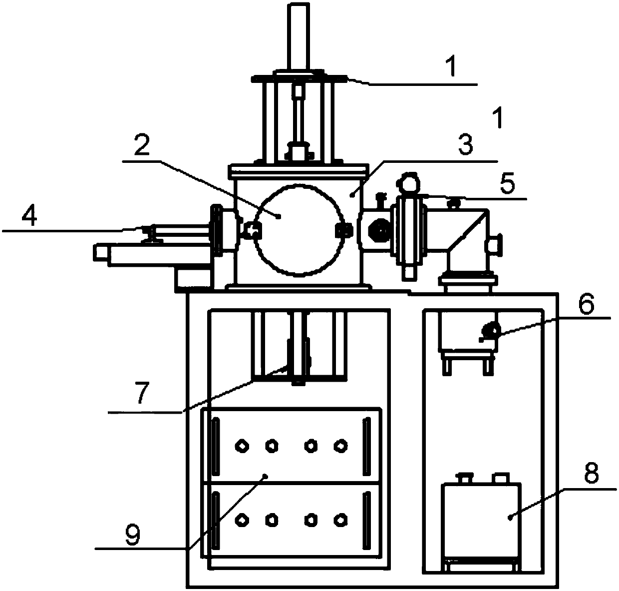
[0055] like figure 1 As shown, the probe type indenter provided by the present invention comprises SPS pressurizing device (1), front door (2), water-cooled vacuum chamber (3), displacement measuring system (4), gate valve (5), molecular pump ( 6), thermocouple lifting mechanism (7), mechanical pump (8), SPS control device (9) and power supply.

[0056] In the pressure system of conventional SPS equipment, the upper graphite column head material used for conducting conductive pressure on the material has limited strength, and cannot heat and pressurize small-diameter samples. The probe-type indenter provided by the invention uses metal tungsten instead of graphite as the indenter material, and its diameter is reduced from 10-20mm to 1mm. At the same time, the tungsten probe type indenter is connected with the lifting device, and the position can be raise...

Embodiment 2

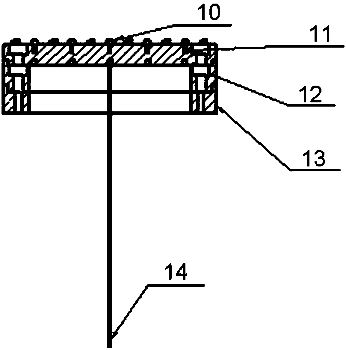
[0058] This embodiment is used to illustrate the structure of the multi-cavity sample tray provided by the present invention.

[0059] like figure 2 As shown, the multi-cavity sample tray provided by the present invention includes a tungsten indenter (10), a graphite sample tray (11), a graphite tray and electrodes (12), an insulating tray (13), and a thermocouple (14). In this embodiment, there are 50 evenly distributed sample grooves on the graphite sample disk, each sample groove has an aperture of 1mm, and each sample groove is matched with a probe-type indenter. The graphite sample plate is placed on the insulating tray, and the graphite tray and electrodes are fixed around it, and the thermocouple passes through the insulating tray from the bottom to connect with the graphite sample plate. Compared with the sintering of a single sample in the graphite mold of the traditional SPS equipment, the graphite mold of this embodiment can place 50 samples with a diameter of 1mm...

Embodiment 3

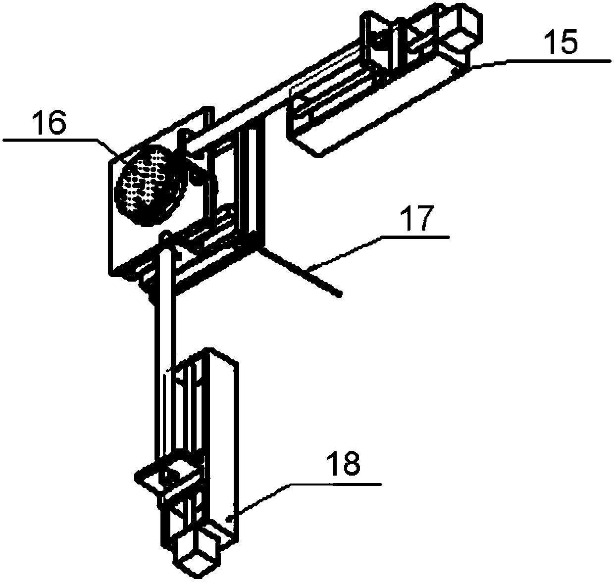
[0061] This embodiment is used to illustrate the structure of the multi-sample tray moving and positioning system provided by the present invention.

[0062] like image 3 As shown, the multi-sample tray moving positioning system provided by the present invention includes a Y-direction moving motor (15), a sample tray (16), a thermocouple (17) and an X-direction moving motor (18).

[0063] The sample tray positioning system mainly uses two sets of servo motors, the X-direction moving motor (18) and the Y-direction moving motor (15) to accurately control the left and right (X direction) and front and rear (Y direction) displacements of the sample tray respectively. When the samples in each hole are sintered, the position of the graphite mold is accurately moved through the positioning system, so that the metal tungsten column head above the mold and the thermocouple below the mold used to measure and control the temperature of the sample material are in a vertically aligned pos...


PUM

PropertyMeasurementUnit
pore sizeaaaaaaaaaa
diameteraaaaaaaaaa

Abstract

The invention provides spark plasma sintering equipment comprising a multi-cavity sample mold. According to the spark plasma sintering equipment, a plurality of samples can be sintered correspondingly, temperature and conditions needed by the different samples can be controlled for the different samples, and a positioning system is configured; and the problem of high-flux high-efficiency preparation of existing commercial spark plasma sintering in new material exploration is solved.

Description

technical field [0001] The invention belongs to the field of material science, and in particular relates to a probe-type high-throughput discharge plasma sintering device. Background technique [0002] Spark plasma sintering (SPS) is a well-developed powder sintering technology, which can sinter the sample during the pressurization process, and discharge plasma is generated instantaneously when the electrode is fed with DC pulse current, making sintering Each particle in the sample uniformly generates its own Joule heat and activates the surface of the particle. In addition, the plasma generated by the pulse current and the pressure during the sintering process are conducive to reducing the sintering temperature of the powder, so that the powder can be sintered quickly and densely, with low voltage , High current characteristics. [0003] At home and abroad, the research on preparing new materials with SPS mainly focuses on: ceramics, cermets, intermetallic compounds, compo...

Claims


Application Information

Patent Timeline
Patent Type & Authority Applications(China)
IPC IPC(8): F27B17/02F27D11/00B22F3/105
CPCB22F3/003B22F3/105F27B17/02F27D11/00F27M2003/04
Inventor 李珊杨佳伟孟磊陆俊赵怀周
Owner INST OF PHYSICS - CHINESE ACAD OF SCI
Learn More