
Dissimilar metal welding method of low-carbon steel and cast iron

A technology of dissimilar metals and welding methods, applied in welding equipment, laser welding equipment, metal processing equipment, etc., can solve problems such as increased cracking tendency, large heat input, fast cooling speed, etc., to improve crack resistance and increase bearing capacity , heat effect is small

Inactive Publication Date: 2019-09-20
CENT OF EXCELLENCE FOR ADVANCED MATERIALS +1
View PDF6 Cites 4 Cited by
  • Summary
  • Abstract
  • Description
  • Claims
  • Application Information

AI Technical Summary

Problems solved by technology

It is very beneficial to control welding deformation, but due to its fast cooling rate, when self-fluxing welding is used, the weld is very easy to form martensitic structure and crack
On the other hand, since laser welds generally have a small form factor (i.e., the weld is deep and narrow), further increasing the cracking tendency
However, if the laser welding method is adopted, the wire feeding device is used to send the welding wire to the weld seam at the same time as the laser welding. Seam composition and structure, reducing weld cracking, but still requires a large heat input, and compared with the traditional MAG welding process, there is no significant improvement

Method used


Image

  • Dissimilar metal welding method of low-carbon steel and cast iron
  • Dissimilar metal welding method of low-carbon steel and cast iron
  • Dissimilar metal welding method of low-carbon steel and cast iron

Examples


Embodiment 1

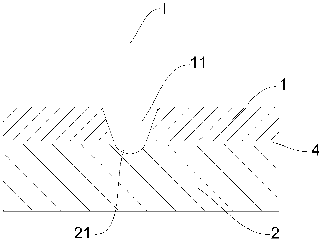
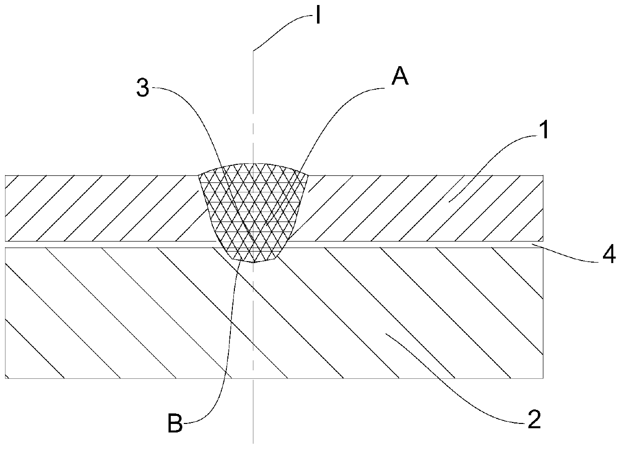
[0031] The laser lap welding method of dissimilar metals of low carbon steel and cast iron comprises the following steps:

[0032] S1. Prepare base metal: low-carbon steel 1 has a carbon content of 0.07wt%, and the thickness of the low-carbon steel is 0.5mm; cast iron 2 has a carbon content of 2wt%, and the thickness of cast iron 2 is 1mm;

[0033] S2. Base metal surface cleaning and assembly: clean the base metal and remove oxides on the surface, that is, clean up the oil stains and rust in the area to be welded, and assemble the surface-cleaned low-carbon steel 1 to be welded with the cast iron 2 from top to bottom. The tooling fixture is fixed to form the parts to be welded, and the assembly gap 4 of the lap joint between the low carbon steel 1 and the cast iron 2 is 0mm;

[0034] S3. Welding process: using galvanometer laser welding head, swinging and self-fluxing welding during welding, laser incident from the side of low carbon steel, laser welding will completely penetr...

Embodiment 2

[0038] The laser lap welding method of dissimilar metals of low carbon steel and cast iron comprises the following steps:

[0039] S1. Prepare base metal: low-carbon steel 1 has a carbon content of 0.3wt%, and the thickness of the low-carbon steel is 4mm; cast iron 2 has a carbon content of 2.5wt%, and the thickness of cast iron 2 is 10mm;

[0040] S2. Base metal surface cleaning and assembly: clean the base metal and remove oxides on the surface, that is, clean up the oil stains and rust in the area to be welded, and assemble the surface-cleaned low-carbon steel 1 to be welded with the cast iron 2 from top to bottom. The tooling fixture is fixed to form the parts to be welded, and the assembly gap 4 of the lap joint between the low carbon steel 1 and the cast iron 2 is 0.2mm;

[0041] S3. Welding process: using galvanometer laser welding head, swinging and self-fluxing welding during welding, laser incident from the side of low carbon steel, laser welding will completely pene...

Embodiment 3

[0045] The laser lap welding method of dissimilar metals of low carbon steel and cast iron comprises the following steps:

[0046] S1. Prepare base metal: low-carbon steel 1 has a carbon content of 0.6wt%, and the thickness of the low-carbon steel is 8mm; cast iron 2 has a carbon content of 4wt%, and the thickness of cast iron 2 is 30mm;

[0047] S2. Base metal surface cleaning and assembly: clean the base metal and remove oxides on the surface, that is, clean up the oil stains and rust in the area to be welded, and assemble the surface-cleaned low-carbon steel 1 to be welded with the cast iron 2 from top to bottom. The tooling fixture is fixed to form the parts to be welded, and the assembly gap 4 of the lap joint between the low carbon steel 1 and the cast iron 2 is 0.5mm;

[0048] S3. Welding process: using galvanometer laser welding head, swinging and self-fluxing welding during welding, laser incident from the side of low carbon steel, laser welding will completely penetr...


PUM

PropertyMeasurementUnit
Thicknessaaaaaaaaaa
Thicknessaaaaaaaaaa
Thicknessaaaaaaaaaa

Abstract

The invention discloses a dissimilar metal welding method of low-carbon steel and cast iron. The method comprises the following steps of S1, preparing of base metal, wherein the carbon content of the low-carbon steel is smaller than or equal to 0.6wt%, the thickness of the low-carbon steel ranges from 0.5 mm to 8 mm, the carbon content of the cast iron ranges from 2wt% to 4wt%, and the thickness of the cast iron is larger than or equal to 1 mm; S2, base metal surface cleaning and assembling, wherein the base metal is cleaned, oxide and oil dirt on the surface are removed, the to-be-welded low-carbon steel and cast iron subjected to surface cleaning are in lap joint and are assembled, a tool clamp is adopted for fixing, a to-be-welded part is formed, and the assembly gap of a lap joint of the low-carbon steel and the cast iron is smaller than or equal to 0.5 mm; and S3, a welding process, wherein a galvanometer laser welding head is adopted, swinging and self-fluxing welding are carried out in the welding process, the low-carbon steel is all subjected to penetration through laser welding, the side surface of the cast iron is partially molten, and the contact faces of the low-carbon steel and the cast iron are subjected to self-fluxing to form a weld bead for fixed connection. According to the method, the welding cost can be reduced, and the anti-cracking performance of the weld bead can be improved; and compared with traditional welding methods such as gas shielding welding, deformation of the welding joint is small, and the obvious technical advantages are achieved.

Description

technical field [0001] The invention relates to a connection technology of dissimilar materials, in particular to a method for welding dissimilar metals of low carbon steel and cast iron. Background technique [0002] Lap joints of mild steel and cast iron dissimilar metals are often found in product structures such as automobiles and air conditioning compressors. Since the carbon content and impurity content of cast iron are generally high, it is very unfavorable for welding, and the welding of low carbon steel and cast iron dissimilar metals is very easy to produce welding cracks. For example, the connection between the low-carbon steel shell of the compressor and the cast iron pump body inside the shell is currently mostly performed by welding methods filled with low-carbon steel welding wire, such as MAG welding. This process requires processing plug welding holes and filling welding materials on the workpiece, and the cost increase; in addition, if the workpiece has se...

Claims


Application Information

Patent Timeline
IPC IPC(8): B23K26/24B23K26/60B23K103/06B23K103/04
CPCB23K26/24B23K26/60B23K2103/04B23K2103/06
Inventor 郑江鹏初铭强张书彦张鹏
Owner CENT OF EXCELLENCE FOR ADVANCED MATERIALS
Learn More