
Circularly polarized differential dielectric resonator array antenna

A technology of dielectric resonators and array antennas, applied in antennas, antenna arrays, antenna grounding devices, etc., can solve the problems of increased loss and cost, single-port antennas cannot be connected by differential circuits, etc. The effect of low level and widened axial ratio bandwidth

Pending Publication Date: 2019-09-17
EAST CHINA NORMAL UNIV
View PDF0 Cites 7 Cited by
  • Summary
  • Abstract
  • Description
  • Claims
  • Application Information

AI Technical Summary

Problems solved by technology

However, the traditional single-port antenna cannot be directly connected to the differential circuit, and must rely on a balun or a 180° hybrid coupler to integrate with the differential circuit
Balun or 180° hybrid coupler will increase the loss and cost, so more and more differential feed antennas are concerned and researched

Method used


Image

  • Circularly polarized differential dielectric resonator array antenna
  • Circularly polarized differential dielectric resonator array antenna
  • Circularly polarized differential dielectric resonator array antenna

Examples


Embodiment

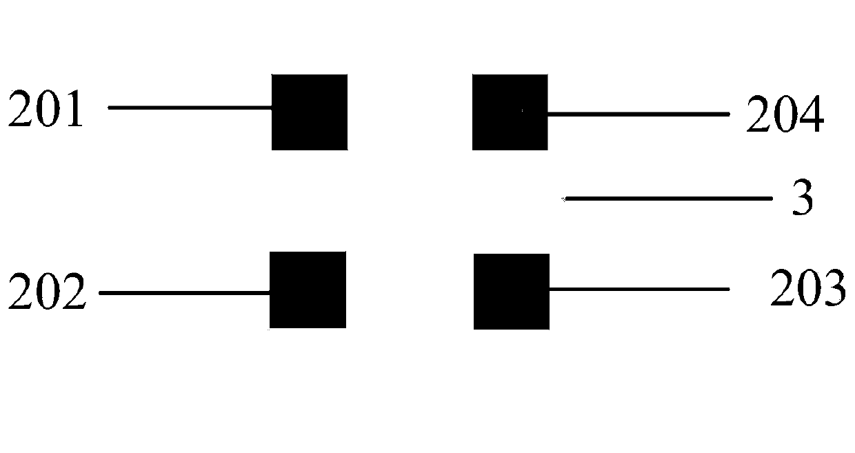
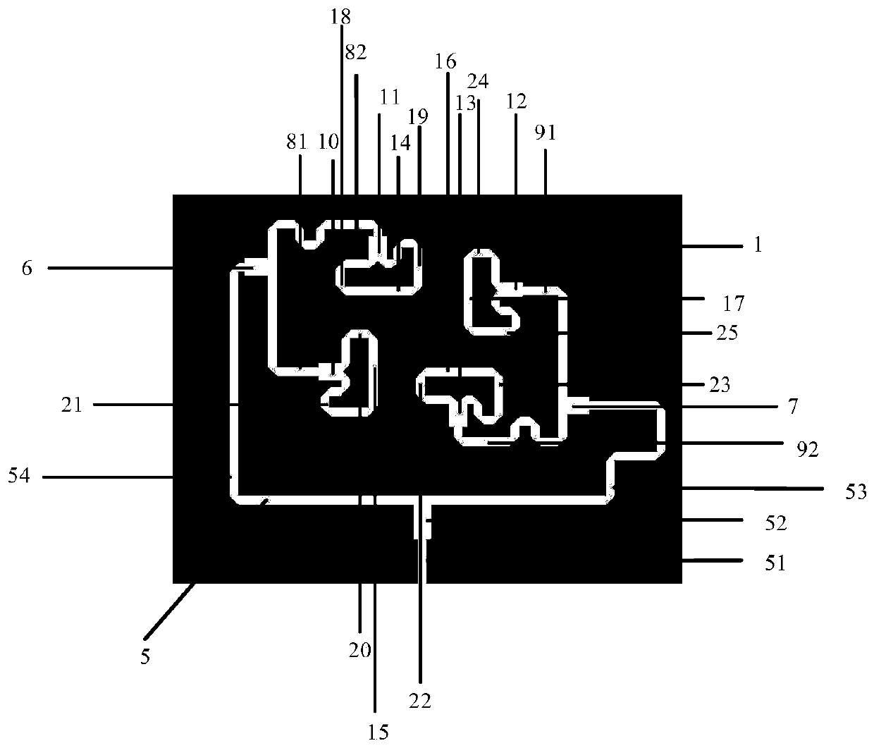
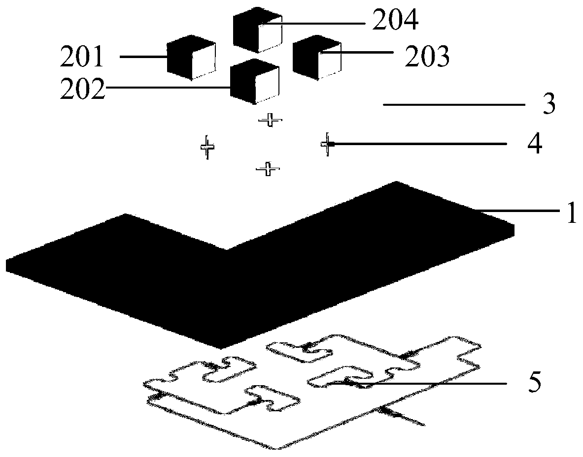
[0033] refer to Figure 1-3 , the differential circularly polarized array antenna of this embodiment is applied in K a-band. It includes a feed structure and four radiation units 201-204; the feed structure includes a dielectric substrate 1, a ground plane 3 provided on the upper surface of the dielectric substrate 1, and a parallel rotating feeder provided on the lower surface of the dielectric substrate 1 The network 5, the ground plane 3 is a metal layer etched on the dielectric substrate 1, and four cross-groove slots 4 are etched on it, and the four cross-groove slots 4 are arranged adjacent to each other and rotated by 90°; the four The radiating units 201-204 are arranged on the four cross slots 4, respectively: the first radiating unit, the second radiating unit, the third radiating unit and the fourth radiating unit; the first radiating unit and the second radiating unit, the The spacing between the third radiating unit and the fourth radiating unit, the second radi...


PUM


Abstract

The invention discloses a circularly polarized differential dielectric resonator array antenna for use in the field of wireless communication. The circularly polarized differential dielectric resonator array antenna comprises a feed structure and four radiating elements. The radiating elements are differential feed circularly polarized rectangular dielectric resonators. The four radiating elements are successively rotated by 0 degree, 90 degrees, 180 degrees and 270 degrees around the center of the array. The feed structure is a parallel sequential rotation feed network and has the same element feed phase and element rotation angle. The array antenna has an impedance bandwidth of 12.1% (25.5 GHz to 28.8 GHz) and a 3dB axial ratio bandwidth of 11.1% (25.95 GHz to 29 GHz). The principal polarization of the array antenna is left-handed circular polarization, and the cross-polarization of the array antenna is right-handed circular polarization. The cross-polarization level on both radiating surfaces can reach below -15dB in a 3dB beam bandwidth. The antenna of the invention has good circular polarization characteristics, a low cross-polarization level, and can be directly integrated with an RF front-end differential circuit because of its differential feed characteristics.

Description

technical field [0001] The invention belongs to the technical field of optics / microwave, wireless communication and test simulation, and in particular relates to a circularly polarized differential dielectric resonator array antenna. Background technique [0002] In recent years, differential microwave circuits have been widely used in the front-end of RF circuits because of their advantages in harmonic suppression, common-mode noise suppression, and modal current cancellation. However, the traditional single-port antenna cannot be directly connected to the differential circuit, and must rely on a balun or a 180° hybrid coupler to integrate with the differential circuit. A balun or a 180° hybrid coupler will increase loss and cost, so more and more differentially fed antennas are being paid attention to and studied. Due to the advantages of dielectric resonator antennas such as low loss, small size, high efficiency, easy excitation and controllable bandwidth, differential d...

Claims


Application Information

Patent Timeline
Patent Type & Authority Applications(China)
IPC IPC(8): H01Q1/48H01Q21/00H01Q21/06H01Q23/00H01P5/12
CPCH01Q21/061H01Q21/005H01Q23/00H01Q1/48H01P5/12
Inventor 冀晓阳翟国华丁军
Owner EAST CHINA NORMAL UNIV
Learn More