
Integrated steam generating device and extractor hood

A technology for a steam generating device and a range hood, which is applied in the directions of steam generation, steam generation method, and oil fume removal, etc., can solve the problems of difficult cleaning, cumbersome on-site assembly, negative performance of the whole machine, etc., and achieves easy installation and disassembly, and easy control. Temperature rise, the effect of ensuring water storage

Pending Publication Date: 2019-09-17
GUANGDONG VANWARD ELECTRIC
View PDF0 Cites 0 Cited by
  • Summary
  • Abstract
  • Description
  • Claims
  • Application Information

AI Technical Summary

Problems solved by technology

[0002] After the range hood is used frequently, a large amount of oil will accumulate on the inner wall of the impeller, and the oil will have a great impact on the dynamic balance of the impeller, which in turn will have a negative impact on the performance of the whole machine
[0003] Many manufacturers on the market have added self-cleaning kinetic energy modules to range hoods. The current known steam cleaning principle is nothing more than pumping cold water into the heating module, heating the heating module to generate steam, and then transporting it to the nozzle through the pipeline. , the impeller is cleaned by spraying high-temperature and high-pressure steam from the nozzle hole; for this self-cleaning principle, a water cup is required to store cold water, and a water pump is required between the cold water cup and the heating module. Heating and evaporating, resulting in many parts, cumbersome on-site assembly and loud noise during cleaning
[0004] To solve this technical problem, there is an integrated steam generating device in the prior art, which integrates the water cup and the heating module. However, due to the large amount of water to be stored in the module, the structure is relatively large, resulting in inconvenient installation and assembly. and the interior is difficult to clean; in addition, the temperature rise in the module is also difficult to control

Method used


Image

  • Integrated steam generating device and extractor hood
  • Integrated steam generating device and extractor hood
  • Integrated steam generating device and extractor hood

Examples


Embodiment Construction

[0037] The specific implementation manners of the present invention will be further described in detail below in conjunction with the accompanying drawings and embodiments. The following examples are used to illustrate the present invention, but are not intended to limit the scope of the present invention.

[0038] In the description of the present invention, it should be understood that the orientation or positional relationship indicated by the terms "upper", "lower", "left", "right", "top", "bottom" etc. Orientation or positional relationship is only for the convenience of describing the present invention and simplifying the description, and does not indicate or imply that the referred device or element must have a specific orientation, be constructed and operated in a specific orientation, and thus should not be construed as a limitation of the present invention. It should be understood that the terms "first", "second", etc. are used in the present invention to describe va...


PUM


Abstract

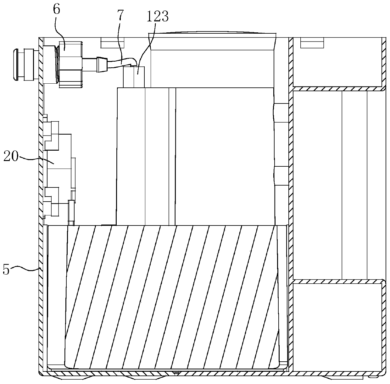
The invention discloses an integrated steam generating device and an extractor hood. The integrated steam generating device comprises a reservoir, a heating body, a temperature protection device and a protection shell. The reservoir comprises a lower shell body and an upper shell body mounted on the upper portion of the lower shell body. A liquid injection opening and a steam outlet are formed in the upper shell body, and a sealing cover body is arranged at the position of the liquid injection opening. The heating body is attached to the outer wall of the lower shell body. The temperature protection device comprises a temperature control switch electrically connected with the heating body and a temperature sensor used for detecting the temperature in the reservoir, and the temperature sensor is electrically connected with the temperature control switch. A connector is mounted on the protection shell, a first airflow passageway is formed in the connector, and the connector communicates with the steam outlet through a connecting pipe. The integrated steam generating device and the extractor hood have the beneficial effects that a water cup and a water pump do not need to be arranged, thus, integrated design is achieved, the structure is simplified, mounting is facilitated, dirt in the reservoir is conveniently cleaned away, the heating efficiency is high, and temperature rise is easy to control.

Description

technical field [0001] The invention relates to the technical field of range hoods, in particular to an integrated steam generating device and a range hood including the same. Background technique [0002] After the range hood is used frequently, a large amount of oil will accumulate on the inner wall of the impeller. The oil will have a great impact on the dynamic balance of the impeller, which in turn will have a negative impact on the performance of the whole machine. [0003] Many manufacturers on the market have added self-cleaning kinetic energy modules to range hoods. The current known steam cleaning principle is nothing more than pumping cold water into the heating module, heating the heating module to generate steam, and then transporting it to the nozzle through the pipeline. , the impeller is cleaned by spraying high-temperature and high-pressure steam from the nozzle hole; for this self-cleaning principle, a water cup is required to store cold water, and a water ...

Claims


Application Information

Patent Timeline
Patent Type & Authority Applications(China)
IPC IPC(8): F22B1/28F22B35/00F24C15/20
CPCF22B1/284F22B35/00F24C15/2057
Inventor 卢楚鹏蒋磊
Owner GUANGDONG VANWARD ELECTRIC
Learn More