
Combustion device for water quality detection

A combustion device and water quality detection technology, applied in the direction of using combustion for chemical analysis, etc., can solve problems such as sticking to the combustion tube, measurement error, etc.

Inactive Publication Date: 2019-09-13
杭州广测环境技术有限公司
View PDF5 Cites 2 Cited by
  • Summary
  • Abstract
  • Description
  • Claims
  • Application Information

AI Technical Summary

Problems solved by technology

[0004] However, when the activated carbon particles adsorbing organic halides are put into a high-temperature combustion furnace for calcination, since the activated carbon particles have just been taken out of the water to be tested and are very wet, they may stick to the combustion tube when they are put in, resulting in measurement results error occurred

Method used


Image

  • Combustion device for water quality detection
  • Combustion device for water quality detection
  • Combustion device for water quality detection

Examples


Embodiment 1

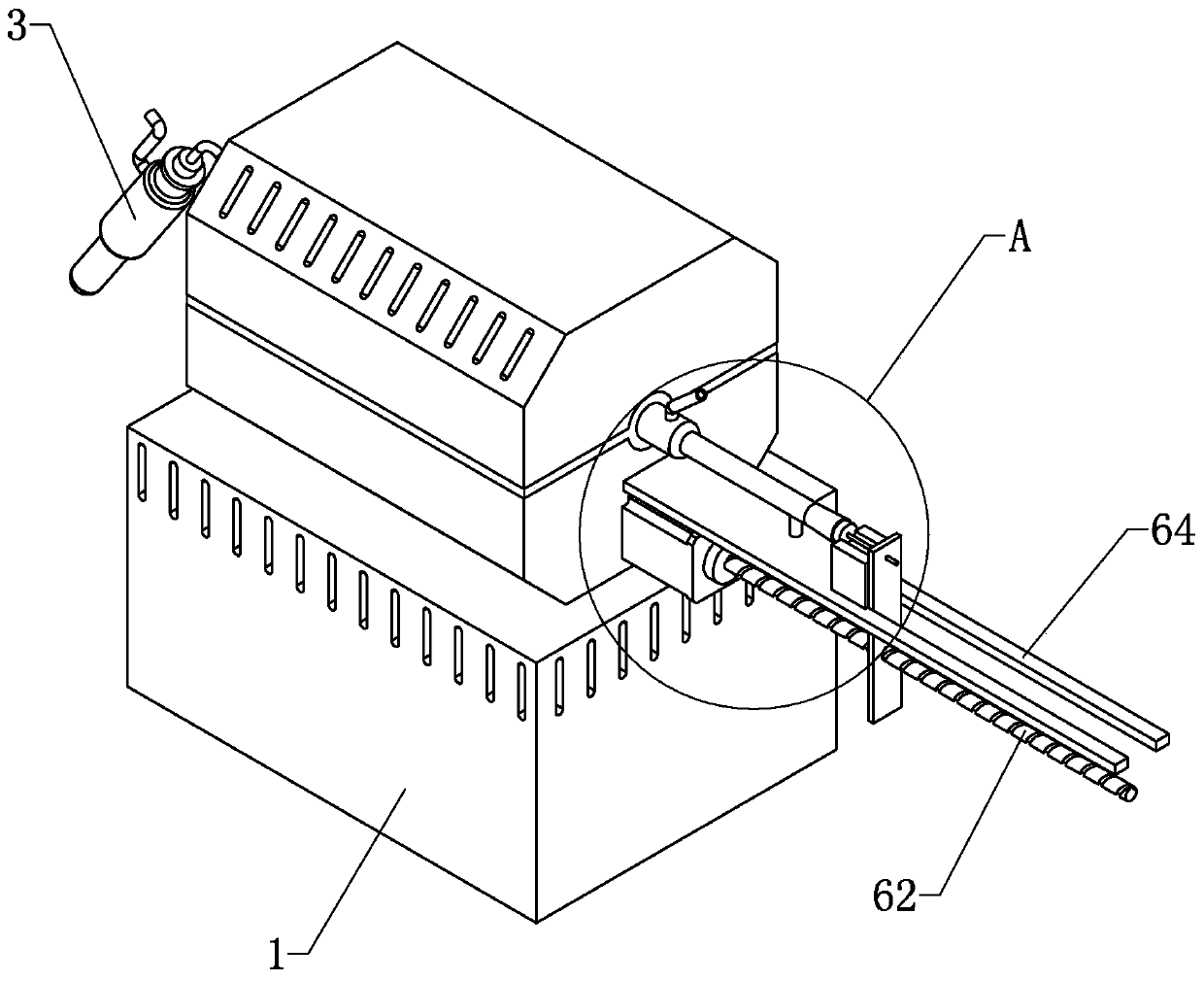
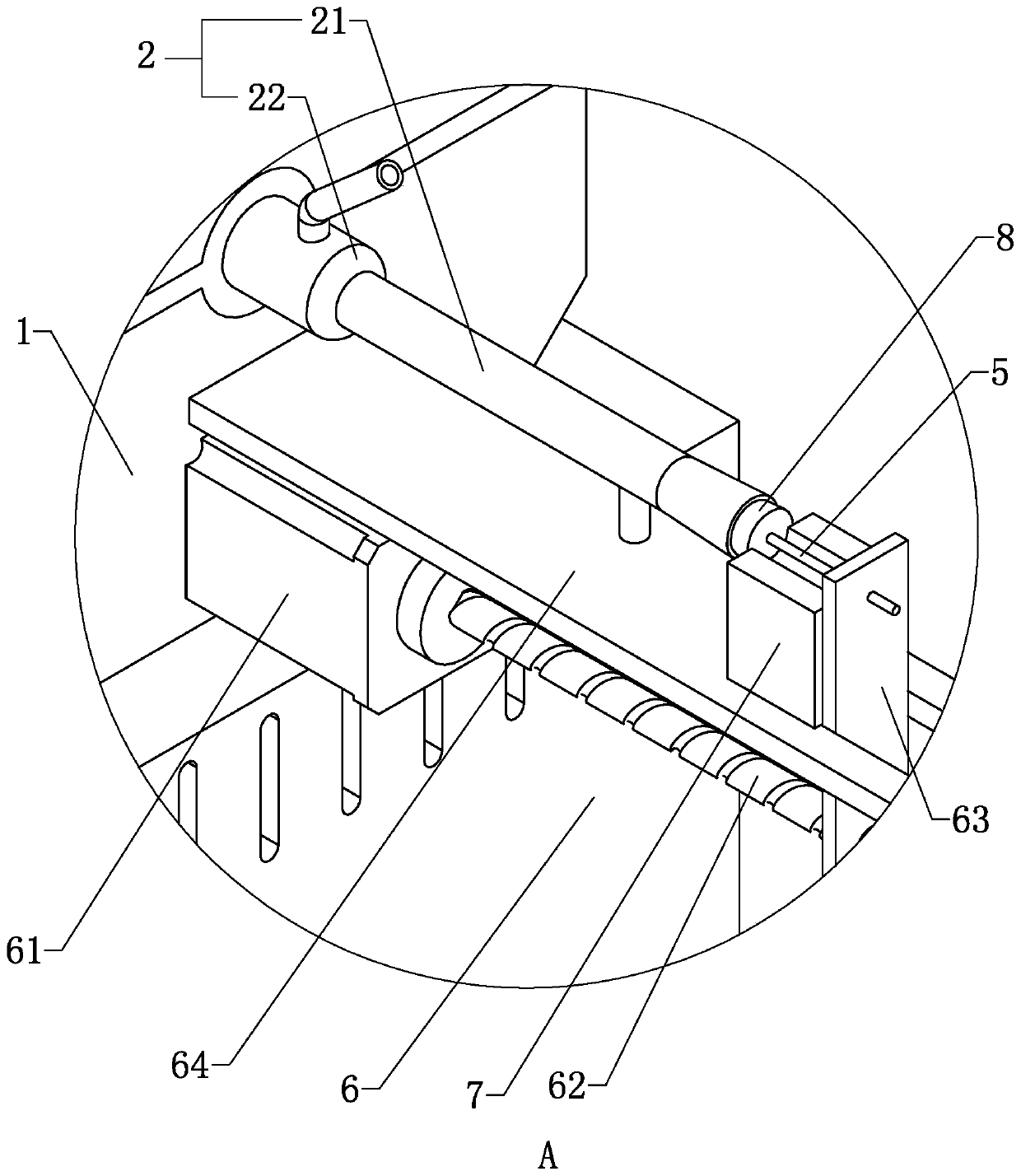
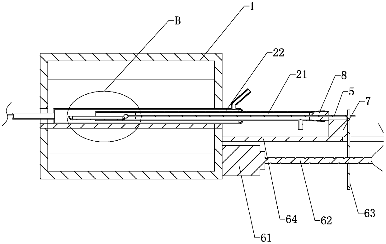
[0040] Embodiment one: a kind of combustion device for water quality detection, such as figure 1 , figure 2 As shown, it includes a combustion furnace 1, a combustion tube 2 passing through the combustion furnace 1, an absorption tube 3 connected to the outlet end of the combustion tube 2, and a sample plate 4 for holding samples ( Figure 4 ), wherein the combustion tube 2 includes a combustion outer tube 22 that runs through the combustion furnace 1, and a combustion inner tube 21 that supports the sample plate 4. When working, both the combustion inner tube 21 and the combustion outer tube 22 need to be fed with oxygen for the sample plate. 4 on the activated carbon combustion.

[0041] The feeding ends of the combustion inner pipe 21 and the combustion outer pipe 22 are not connected, and an air inlet is respectively provided at the feeding ends. Wherein the air intake of combustion inner pipe 21 is arranged vertically, and is positioned at the bottom of combustion inne...

Embodiment 2

[0053] Embodiment two: a kind of combustion device for water quality detection, such as Figure 5 As shown, when the push rod 5 moves in and out, the sealing relationship of the combustion tube 2 must be ensured, so the sealing plug 8 is used to seal the opening of the combustion tube 2 at the feed end.

[0054] The push rod 5 passes through the sealing plug 8 and is slidably connected with the sealing plug 8 , and friction stripes are provided at the abutment between the sealing plug 8 and the push rod 5 to increase the friction force. Therefore, when it is necessary to use the sealing plug 8 to close the combustion tube 2, the friction stripes drive the sealing plug 8 to move toward the combustion tube 2 until the sealing plug 8 is tightly pressed against the combustion tube 2, and one end of the sealing plug 8 is located in the combustion tube 2, and the other One end is located outside the combustion tube 2.

[0055] One end of the sealing plug 8 located in the combustion...


PUM


Abstract

The invention relates to the field of the water quality detection, more specifically, a combustion device for water detection. The device aims at solving the problem that the measurement error occurssince the activated carbon is likely to adhere a combustion tube wall when being placed in a sample plate. The technical scheme key point is that one combustion device for the water quality detectioncomprises a combustion furnace, a combustion tube penetrating through the combustion furnace, an absorption tube connected to a piercing end of the combustion tube, and a sample plate for placing a sample; the sample plate is stored in the combustion tube, and connected with a push rod; the push rod pierces the combustion tube along a length direction of the combustion tube, and the piercing end of the push rod is connected with a driving mechanism for driving the push rod to move along the length direction of the combustion tube; and a support plate for supporting the sample plate is arrangedat a port of the combustion tube. Through the design of the driving mechanism, the sample plate can automatically extend out from the combustion tube, thereby conveniently, accurately and directly filling the activated carbon in the sample plate.

Description

technical field [0001] The invention relates to the field of water quality detection, more specifically, it relates to a combustion device for water quality detection. Background technique [0002] AOX refers to Absorbable Organic Halogen (Absorbable Organic Halogen), because of its teratogenic, carcinogenic and mutagenic properties, the determination of AOX organic halogens (organic chlorine, organic fluorine, organic bromine) has become an important water quality control in the environmental testing industry index. [0003] The determination of adsorbable organic halides in water includes microcoulometry (GB / T15959-1995) and ion chromatography (HJ / T83-2001). Both methods need to use a core component - a high temperature Combustion furnace (temperature set at 950°C). [0004] However, when the activated carbon particles adsorbing organic halides are put into a high-temperature combustion furnace for calcination, since the activated carbon particles have just been taken ou...

Claims


Application Information

Patent Timeline
Patent Type & Authority Applications(China)
IPC IPC(8): G01N31/12
CPCG01N31/12
Inventor 邵建林赖志贤王晶晶
Owner 杭州广测环境技术有限公司
Learn More