Automatic plate shearing machine for machining electric device shell
A shearing machine and electrical device technology, applied in metal processing equipment, shearing machine equipment, shearing devices, etc., can solve problems such as reducing the practicability of automatic shearing machines, staff damage, equipment vibration, etc., and achieve convenient location changes. , The effect of preventing collision and convenient clamping
- Summary
- Abstract
- Description
- Claims
- Application Information
AI Technical Summary
Problems solved by technology
Method used
Image

Examples
Embodiment 1
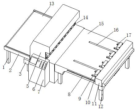
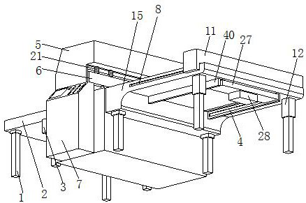
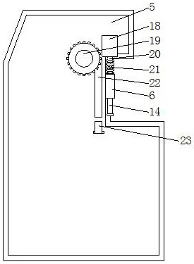
[0026] see Figure 1-6 , the present invention provides a technical solution: an automatic shearing machine for electrical device housing processing, including a shearing machine body 5, an installation box 11 and a movable block 31, and the inner cavity of the shearing machine body 5 is fixedly equipped with a hydraulic Cylinder 18, the hydraulic end of the hydraulic cylinder 18 is fixedly installed with a first telescopic rod 20, the end of the first telescopic rod 20 away from the hydraulic cylinder 18 is fixedly installed with a connecting plate 6, and the side of the connecting plate 6 away from the first telescopic rod 20 is fixedly installed Fixed post 14 is arranged, and first telescopic spring 21 is fixedly installed on the outside of the first telescopic link 20, and four connecting posts 29 are fixedly installed on the bottom of installation box 11, and one end of four connecting posts 29 away from installation box 11 is fixedly installed with installation Plate 27,...
Embodiment 2
[0029] Such as Figure 1-6 As shown, on the basis of Embodiment 1, the present invention provides a technical solution: the inner cavity of the shearing machine body 5 is fixedly installed with a second driving motor 19, and the outer side of the driving end of the second driving motor 19 is fixedly installed with a turntable 39, The top of the rotating disk 39 is fixedly equipped with a Z-shaped articulated rod 38, and one end of the Z-shaped articulated rod 38 away from the rotating disk 39 is fixedly installed with a clamping block 37, and the opposite side of the mounting clamping block 37 is fixedly equipped with an upper shearing blade 22. The inner cavity of the trigger body 5 is fixedly equipped with a lower shearing blade 23, and the front of the shearing machine body 5 is fixedly equipped with a transmission frame 2, and the internal activity of the transmission frame 2 is equipped with a transmission device 13, and one part of the transmission frame 2 The first driv...
Embodiment 3
[0032] Such as Figure 1-6 As shown, on the basis of Embodiment 1 and Embodiment 2, the present invention provides a technical solution: rubber pads 36 are fixedly installed on the opposite sides of the upper clamping plate 17 and the lower clamping plate 9, and the movable block 31 and the clamping plate Four limit blocks 33 are fixedly installed on opposite sides of 34 .
[0033] In this embodiment, the role of the rubber pad 36 is to prevent the upper clamping plate 17 and the lower clamping plate 9 from causing damage to the electrical device housing when clamping the electrical device housing, so as to cause economic losses. The limit block 33 The effect of this is to prevent the collision between the movable block 31 and the splint 34, avoiding the collision between the equipment, causing equipment damage, so as to affect the service life of the shearing machine equipment.
PUM
 Abstract
Description
Claims
Application Information
 - R&D
- Intellectual Property
- Life Sciences
- Materials
- Tech Scout
- Unparalleled Data Quality
- Higher Quality Content
- 60% Fewer Hallucinations
Browse by: Latest US Patents, China's latest patents, Technical Efficacy Thesaurus, Application Domain, Technology Topic, Popular Technical Reports.
© 2025 PatSnap. All rights reserved.Legal|Privacy policy|Modern Slavery Act Transparency Statement|Sitemap|About US| Contact US: help@patsnap.com