
E-type inductor automatic assembly machine and assembly method thereof

An automatic assembly machine, automatic assembly technology, applied in the direction of inductance/transformer/magnet manufacturing, circuits, electrical components, etc., can solve problems such as low production efficiency, improve production efficiency, ensure position accuracy, and solve problems of low production efficiency. Effect

Inactive Publication Date: 2018-11-06
CHANGXING SOFITEL ELECTRONICS
View PDF0 Cites 1 Cited by
  • Summary
  • Abstract
  • Description
  • Claims
  • Application Information

AI Technical Summary

Problems solved by technology

[0003] The purpose of the present invention is to address the deficiencies of the prior art, to provide an E-shaped inductance automatic assembly machine and its assembly method, through the special structural settings of the feeding assembly and the loading assembly, the magnetic core A is synchronized during the transfer process Realize the rapid assembly of magnetic core A, coil body and magnetic core B, combined with the transmission settings of positioning components, feeding components and film winding components, realize the rapid assembly and output of E-shaped inductors, and solve the problems existing in the prior art Technical problems with low production efficiency

Method used


Image

  • E-type inductor automatic assembly machine and assembly method thereof
  • E-type inductor automatic assembly machine and assembly method thereof
  • E-type inductor automatic assembly machine and assembly method thereof

Examples


Embodiment 1

[0046] Embodiments of the present invention are described in detail below, examples of which are shown in the drawings, wherein the same or similar reference numerals designate the same or similar elements or elements having the same or similar functions throughout. The embodiments described below by referring to the figures are exemplary and are intended to explain the present invention and should not be construed as limiting the present invention.

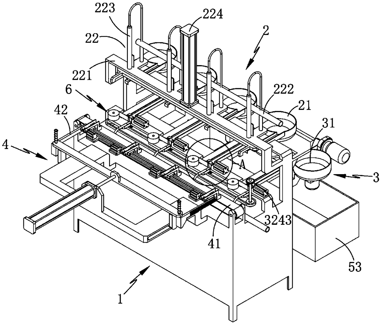
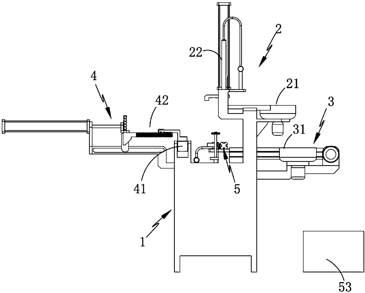
[0047] like figure 1 , 2 , 3, 4 and 5, an E-shaped inductance automatic assembly machine, including a frame 1, is characterized in that it also includes:

[0048] The magnetic core A transfer mechanism 2, the magnetic core A transfer mechanism 2 includes a sorting component I21 and a feeding component 22 located above the sorting component I21; through the sorting component I21, a number of magnetic cores A in it are sorted in sequence, and then The feeding assembly 22 transfers the sorted magnetic cores A downward one by one i...

Embodiment 2

[0058] Among them such as figure 1 and 10 As shown, the parts that are the same as or corresponding to those in the first embodiment adopt the reference numerals corresponding to the first embodiment. For the sake of simplicity, only the differences from the first embodiment are described below; the differences between the second embodiment and the first embodiment The position is: the feeding assembly 42 includes a moving frame A421 that moves horizontally along the horizontal chute 11 provided on the frame 1, a vertical moving frame 422 arranged on the moving frame A421, and arranged side by side on the vertical moving frame A421. A plurality of feeding parts 423 on the straight moving frame 422, a driving member 424 driving the reciprocating motion of the moving frame A421, and a transmission member 425 arranged on the vertical moving frame 422 and intermittently connected to the transmission part 324, In this embodiment, the transmission member 425 is provided as a rack a...

Embodiment 3

[0062] Among them such as figure 1 , 5As shown in and 9, the parts identical or corresponding to those in the second embodiment adopt the reference numerals corresponding to the second embodiment. For the sake of simplicity, only the differences between the second embodiment and the second embodiment are described below; The difference is that it also includes a film winding assembly 6 arranged outside the positioning assembly 32, which includes a film roll 61, a support column 62 positioned on one side of the film roll 61 to support the film, and a support column 62 arranged between the support column 62 and the film roll. The cutting knife 63 that cuts the film between the positioning platforms 322 and the air pipe 64 that is arranged on one side of the support column 62 to carry out intermittent blowing and air suction to the film, the cutting knife 63 and the pushing assembly 51 is connected by transmission and the direction of movement of the two is opposite. In this emb...


PUM


Abstract

The invention relates to the field of inductor production technology, in particular to an E-type inductor automatic assembly machine and an assembly method thereof. The E-type inductor automatic assembly machine comprises a magnetic core A transfer mechanism, a magnetic core B transfer mechanism, a coil body transfer mechanism and an output mechanism, wherein the magnetic core A transfer mechanismcomprises a sorting assembly I and a feeding assembly; the magnetic core B transfer mechanism comprises a sorting assembly II and a positioning assembly; the coil body transfer mechanism comprises aninput assembly and a loading assembly; and the output mechanism comprises a push assembly, a transfer assembly and a collection bin at the tail end of the transfer assembly. Through special structural setting of the feeding assembly and the loading assembly, rapid assembly of a magnetic core A, a coil body and a magnetic core B is realized synchronously in a transfer process of the magnetic coreA; rapid assembly film winding and outputting of an E-type inductor are realized; and the technical problem of low production efficiency in the prior art is solved.

Description

technical field [0001] The invention relates to the technical field of inductance production, in particular to an E-shaped inductance automatic assembly machine and an assembly method thereof. Background technique [0002] Inductors, transformers and other industries, products of many specifications need to be assembled and wound with film or tape. At present, the inductance production industry mostly works on a single machine. After the inductance components are assembled in pairs, they are transferred to the assembly station for overall assembly, and then the assembled assembly is wound by the film winding station; however, due to the E-shaped The magnetic core A, the coil body and the magnetic core B in the inductor are all clearance fits, so the traditional assembly method is likely to cause scattering after the initial assembly or displacement variables between the two, resulting in the need to adjust the front in the subsequent assembly process. After an assembly is c...

Claims


Application Information

Patent Timeline
Patent Type & Authority Applications(China)
IPC IPC(8): H01F41/00H01F41/02H01F41/04
CPCH01F41/005H01F41/02H01F41/04
Inventor 沈国栋
Owner CHANGXING SOFITEL ELECTRONICS
Learn More