Multifunctional straw returning machine

A multi-functional, straw technology, used in harvesters, crop processors, agricultural machinery and implements, etc., can solve the problems of single structure and poor applicability, and achieve the effect of increasing applicability and eliminating dust.

Pending Publication Date: 2019-09-10
HENAN HAOFENG AGRI EQUIP CO LTD
View PDF0 Cites 0 Cited by
  • Summary
  • Abstract
  • Description
  • Claims
  • Application Information

AI Technical Summary

Problems solved by technology

[0002] Returning to the field is a measure to improve soil fertility and increase production that is generally valued in the world today. It can increase fertilizer and increase production while eliminating the air pollution caused by straw burning. Returning straw to the field can increase soil organic matter and improve soil structure. The soil is loose, the porosity is increased, the capacity is reduced, and the microbial activity and the development of the root system of the crop are promoted. The straw returning to the field has a significant effect on increasing fertilizer and production, and generally can increase production by 5% to 10%. The straw returning machine is used as a field returning machine , and it is more and more widely used in the field of agriculture; however, due to the relatively simple structure of the existing straw returning machines, the applicability is poor. Therefore, in order to solve the above problems, it is necessary to develop a multifunctional straw returning machine with reasonable structure and good applicability.

Method used


Image

  • Multifunctional straw returning machine
  • Multifunctional straw returning machine
  • Multifunctional straw returning machine

Examples


Embodiment

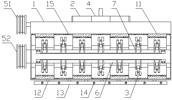
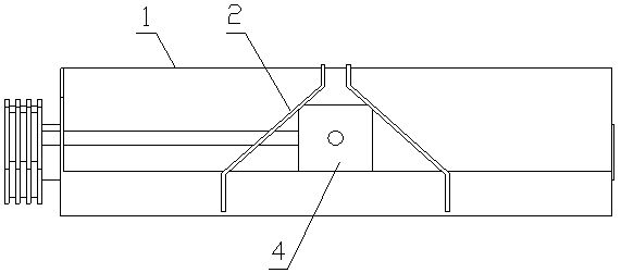
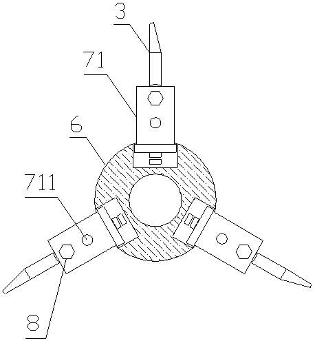
[0025] Example: such as figure 1 , figure 2 As shown, a multi-functional straw returning machine includes a machine body 1, a draw bar 2 and a crushing knife 3. A gearbox 4 is arranged in the middle of the inner surface of the machine body 1. There are two draw bars 2, which are symmetrical Set on both sides of the gearbox 4, the left end of the body 1 is provided with a pulley 5, the pulley 5 includes a pulley a51 and a pulley b52, the pulley a51 and the pulley b52 are connected to each other through a V-belt, and the pulley a51 passes through a rotating shaft Connected with the gearbox 4, the body 1 is provided with a rotating shaft 6, and the two ends of the rotating shaft 6 are respectively connected to the body 1 through bearings, wherein the left end of the rotating shaft 6 protrudes to the outside of the body 1 and is fixed to the wheel b52 Socketing, the outer surface of the rotating shaft 6 is uniformly provided with a tool holder 7 along its circumferential directi...


PUM


Abstract

The invention relates to a multifunctional straw returning machine, which comprises a machine body, traction rods and crushing knifes, wherein a gearbox is arranged in the middle of the inner side surface of the machine body; the traction rods are symmetrically arranged on both sides of the gearbox; belt pulleys are arranged at the left end of the machine body; the belt pulleys comprise a pulley aand a pulley b; the pulley a is connected with the gearbox through a rotary shaft; rotary shafts are arranged inside the machine body; both ends of the rotary shafts are respectively connected with the machine body through bearings in a rotary manner; the left end of one rotary shaft protrudes to the outside of the machine body and is fixedly connected to the pulley b in a sleeved manner; multiple groups of knife racks are arranged on the outer surface of the rotary shafts; each group of the knife racks comprises two fixing plate; two connecting holes are formed in each the fixing plate; eachthe crushing knife is positioned between the two fixing plates; a connecting bolt is arranged at the lower end of the grinding knife; a plurality of arc-shaped stoppers are uniformly arranged on theinner wall of the machine body along the length direction of the grinding knifes; and the thickness of the stoppers is the same as the linear distance between hole centers of the two connecting holeson each the fixing plate. The machine has the advantages of reasonable structure and good applicability.

Description

technical field [0001] The invention belongs to the field of agricultural machinery, and in particular relates to a multifunctional straw returning machine. Background technique [0002] Returning to the field is a measure to improve soil fertility and increase production that is generally valued in the world today. It can increase fertilizer and increase production while eliminating the air pollution caused by straw burning. Returning straw to the field can increase soil organic matter and improve soil structure. The soil is loose, the porosity is increased, the capacity is reduced, and the microbial activity and the development of the root system of the crop are promoted. The straw returning to the field has a significant effect on increasing fertilizer and production, and generally can increase production by 5% to 10%. The straw returning machine is used as a field returning machine , and it is more and more widely used in the field of agriculture; however, due to the rel...

Claims


Application Information

Patent Timeline
IPC IPC(8): A01D82/00B01D47/06
CPCA01D82/00B01D47/06Y02P60/20
Inventor 刘俊锋张华敏沈云亭袁鹏飞
Owner HENAN HAOFENG AGRI EQUIP CO LTD
Why Eureka
Try Eureka