Tool radius directional compensation algorithm for slow slide servo turning of complex curved surface

A complex surface and tool radius technology, applied in the field of mechanical processing, can solve problems such as 'point coordinates are not easy to solve, and achieve the effect of solving solution efficiency and solution accuracy

Active Publication Date: 2019-09-06
INST OF MACHINERY MFG TECH CHINA ACAD OF ENG PHYSICS
View PDF5 Cites 2 Cited by
  • Summary
  • Abstract
  • Description
  • Claims
  • Application Information

AI Technical Summary

Problems solved by technology

[0004] The technical problem to be solved by the present invention is the problem that the O' point coordinates are difficult to solve by directional compensation. Compensation algo

Method used


Image

  • Tool radius directional compensation algorithm for slow slide servo turning of complex curved surface
  • Tool radius directional compensation algorithm for slow slide servo turning of complex curved surface
  • Tool radius directional compensation algorithm for slow slide servo turning of complex curved surface

Examples


Embodiment 1

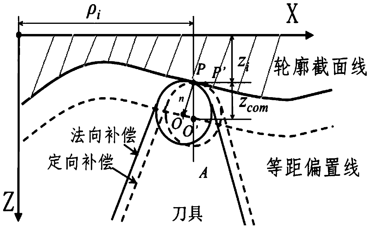
[0025] Such as figure 1 , figure 2 As shown, the present invention is used for the tool radius orientation compensation algorithm of complex curved surface slow tool servo turning, comprising the following steps:

[0026] Step 1: Establish an XZ coordinate system on the profile section curve;

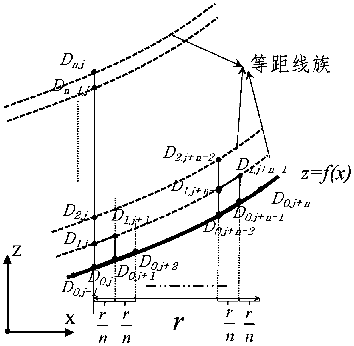
[0027] Step 2: Perform point discretization on the profile section curve to obtain discrete points, and use D for the Z coordinate value i,j Indicates that i in the subscript indicates the number of times of compensation, and j indicates the point sequence; from figure 2 It can be seen from the figure that when i=0, the coordinate point is the point on the original curve without compensation, and the difference between adjacent abscissas of the original point is r / n. When i=n, ​​it represents the final compensation point ;

[0028] Step 3: At the compensated point D 0,j , get subdivision radius compensation point D 1,j ;

[0029] Step 4: Repeat the third step above until the fi...

Embodiment 2

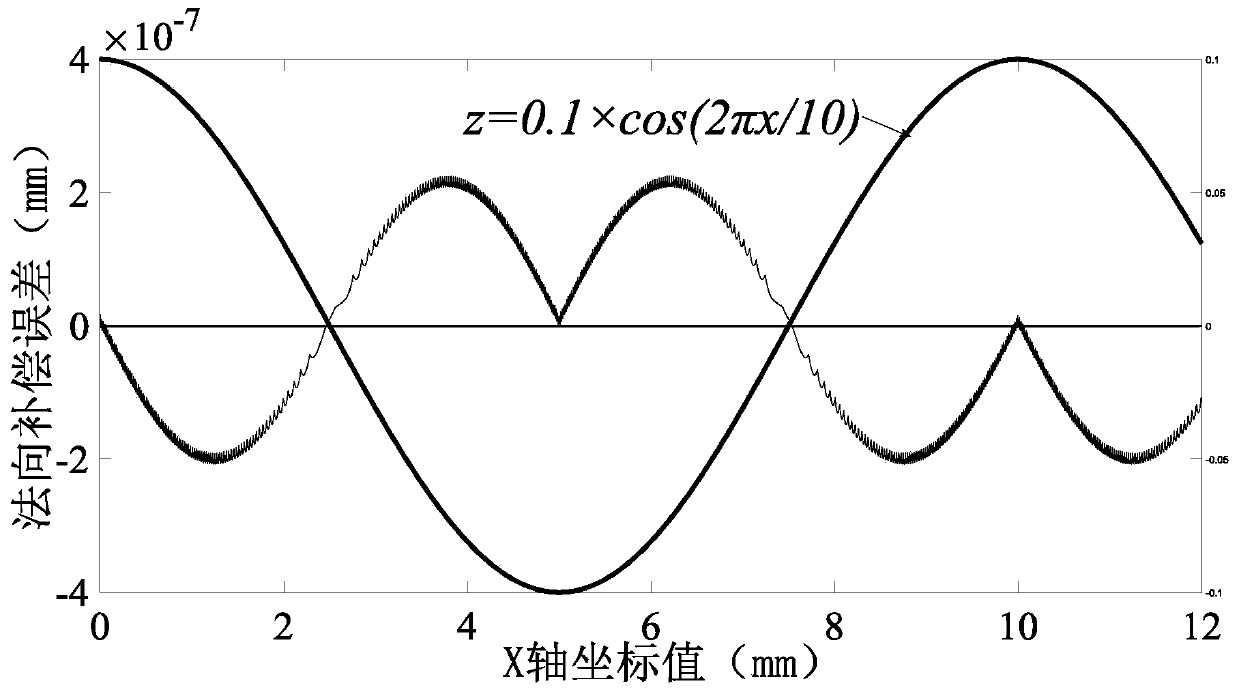
[0034] The first-order continuous function equation is z=0.1*cos(2πx / 10)mm, the tool radius is r=0.3mm, and the value range of x is [0,12]. The compensation error value when taking different values ​​of n is as follows, such as image 3 As shown, when n=256, the cosine curve orientation compensation error value.

[0035] The following table shows the normal compensation error for different n values

[0036] n value 1 4 16 64 256 Compensation error(nm) 53.7 13.9 3.91 0.98 0.23

[0037] It can be seen from the above table that the maximum compensation error value is inversely proportional to n, and the algorithm has been verified.

Embodiment 3

[0039] For some types of optical complex surfaces, such as optical arrays, the cross-sectional lines of the surface often have the characteristics of first-order discontinuity, and the use of normal compensation may produce abrupt points. Figure 4 Shown as a calculation example of an equidistant offset curve family obtained by performing orientation compensation on a polyline segment, r is the offset amount, and the positive and negative values ​​represent the offset direction. Due to the averaging effect of the algorithm, it can be seen that the sudden change points (points 1 and 3) of the original curve will form a natural smooth transition (points 2 and 4) after compensation.


PUM


Abstract

The invention discloses a tool radius directional compensation algorithm for slow slide servo turning of a complex curved surface. The tool radius directional compensation algorithm comprises the following steps of: firstly, establishing an XZ coordinate system on a contour section curve; carrying out point position discrete processing on the contour section curve to obtain discrete point positions, representing a Z coordinate value with Di,j, wherein in subscripts, i represents times of compensation and j represents a point sequence; then obtaining a subdivided radius compensation point D1,jat a compensated point D0,j; repeating the steps until obtaining a final compensated point Dn,j; and finally, obtaining the Z coordinate value of Dn,j at D0,j. according to the invention, the curve isdirectly subject to discrete subdivision, and the compensated point is obtained on the basis of the rapid directional compensation algorithm; and compared to existing algorithms in the current literature, the tool radius directional compensation algorithm only needs to carry out square and radication operations without carrying out equation solution or curve reconstruction, meanwhile, is also applicable to directional compensation of a first-order discontinuous function, meets the requirements of actual ultraprecision machining engineering application and solves problems of solving efficiencyand solving accuracy.

Description

technical field [0001] The invention relates to the technical field of mechanical processing, in particular to a tool radius orientation compensation algorithm for slow tool servo turning of complex curved surfaces. Background technique [0002] In order to realize slow tool servo machining of complex curved surfaces, machining path planning is an important part. Generally speaking, path planning needs to consider issues such as tool contact trajectory planning, tool compensation algorithm, motion axis acceleration and deceleration control, interpolation error analysis, machining tool interference, etc. Among them, the classic method of tool compensation algorithm is to use the normal radius compensation algorithm (or called isometric method), has been widely used. Under the selection of different tool arc radius compensation algorithms, the formed machining trajectory will have an impact on the motion of the machine tool. The classic normal compensation algorithm will gene...

Claims


Application Information

Patent Timeline
IPC IPC(8): G05B19/404
CPCG05B19/404
Inventor 李佳伟
Owner INST OF MACHINERY MFG TECH CHINA ACAD OF ENG PHYSICS
Why Eureka
Try Eureka