
System for preparation of bio-oil, activated carbon and synthetic gas by microwave pyrolysis

A technology for synthesis gas and bio-oil, which is used in bio-fuel, petroleum industry, indirect heating and dry distillation, etc., can solve the problems of harsh particle size and moisture content of raw materials, no temperature detection system designed, and poor quality of pyrolysis products. Achieve good industrial value, sufficient and uniform pyrolysis reaction, and simple design

Inactive Publication Date: 2019-09-03
JIANGSU UNIV
View PDF8 Cites 5 Cited by
  • Summary
  • Abstract
  • Description
  • Claims
  • Application Information

AI Technical Summary

Problems solved by technology

(Problems in ordinary biomass pyrolysis reactors: strict requirements on raw material particle size and moisture content, poor heat transfer efficiency, poor quality of pyrolysis products (mixed components), long reaction time (energy consumption), etc.)
The microwave reactor pyrolysis system circulates a lot of gas, but the actual operation process is too cumbersome and inconvenient to operate, and the design of the spouted fluidized bed also includes an activated carbon cooling tower, which requires high equipment and greatly increases the cost. Screw feeding is also used. This feeding method is easy to jam the material and damage the feeding bearing, which is not conducive to actual production. There is also no design of the temperature detection system, and there is no feedback on the temperature.
The processing method of syngas is combustion and circulation, the utilization rate of syngas is too low, and the economy is poor

Method used


Image

  • System for preparation of bio-oil, activated carbon and synthetic gas by microwave pyrolysis

Examples


Embodiment 1

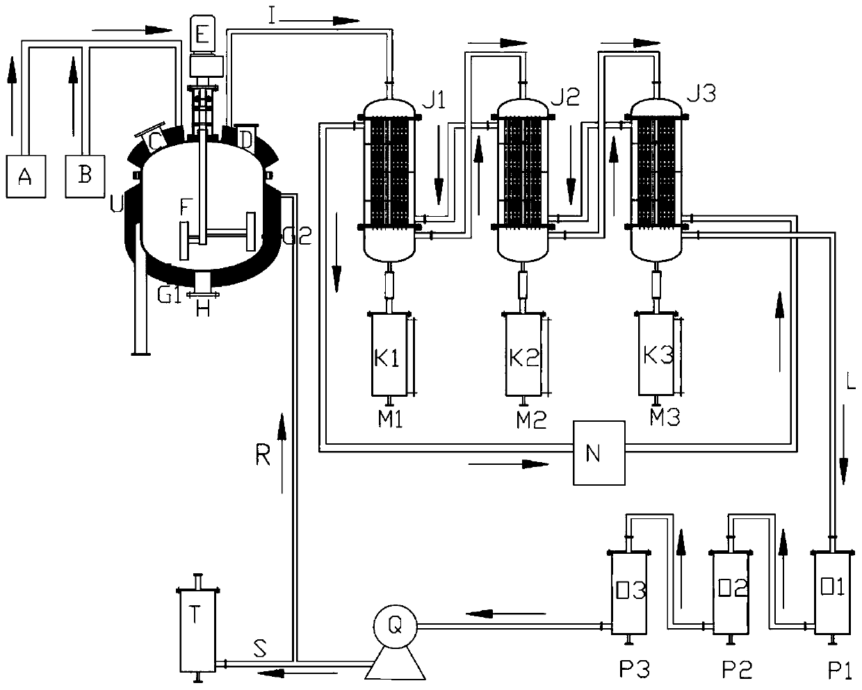
[0030] Before the reaction starts, feed material (50KG poplar wood particles) through the material inlet valve C, close the valve, open the nitrogen generator A, exhaust the whole system, close the nitrogen generator A, and turn on the microwave generator in the microwave reactor D (3 microwave generators, power of each microwave generator is 1500W) and helical gear motor E, so that the stirrer F can be used to stir while the system is heating, and it can be carried out by thermocouple temperature measuring tubes G1 and 2 The temperature measurement is fed back to the PLC controller to control the power of the microwave generator. When the temperature rises to 450°C, the channel I of the pyrolysis gas pipeline is opened to allow the pyrolysis gas to pass through the three-stage condenser J1, 2, and 3 (circulation in the condenser The water temperature is 5°C), so that the pyrolysis gas is condensed to generate bio-oil (bio-oil yield is 75%), which is then collected into bio-oil...


PUM

PropertyMeasurementUnit
specific surface areaaaaaaaaaaa

Abstract

The invention relates to a system for preparation of bio-oil, activated carbon and synthetic gas by microwave pyrolysis. The system consists of a nitrogen generator, a water vapor generator, a microwave pyrolysis reactor, condensers, bio-oil storage tanks, synthetic gas buffer tanks, a suction fan and a synthetic gas storage tank. The nitrogen generator and the water vapor generator are connectedto an air inlet at the top of a microwave generator through a pipeline, an air outlet at the top of the microwave generator is connected to the condensers through a pyrolysis gas pipeline, the bottomsof the condensers are connected to the bio-oil storage tanks, the air outlets of the condensers are connected to the synthetic gas buffer tanks through a pipeline, circulating water cools in a circulating water refrigerating machine and then flows through the condensers through a pipeline for circulating cooling, the suction fan is connected to the synthetic gas buffer tanks and the synthetic gasstorage tank, one part of the synthetic gas is stored by the storage tank, and the other part of the synthetic gas is returned as the gas for activating biochar to the microwave pyrolysis reactor through a pipeline to convert biochar into activated carbon.

Description

technical field [0001] The invention relates to a system for preparing bio-oil, active carbon and synthesis gas by microwave pyrolysis. Background technique [0002] Nowadays, energy problems are becoming more serious with the increase of human activities and social development. Petroleum fuel resources are recognized as the most valuable finite natural energy. Due to its current consumption rate higher than the renewable cycle, the world's petroleum resources are expected to be depleted after 2042, regardless of the projected growth of petroleum fuels. In addition, the extensive use of fossil fuel resources will increase the emission of harmful pollutants, such as sulfur dioxide, nitrogen oxides and carbon dioxide, which will bring a series of environmental problems. Carbon dioxide and other gases produced during the use of petroleum fuels are used as greenhouse gases, which will cause global warming. Fossil fuels are gradually unable to meet human needs, and it is urgen...

Claims


Application Information

Patent Timeline
Patent Type & Authority Applications(China)
IPC IPC(8): C10B53/00C10B53/02C10B47/18
CPCC10B47/18C10B53/00C10B53/02Y02E50/10
Inventor 卜权陈坤孔祥海
Owner JIANGSU UNIV
Learn More