
Fractional N frequency division circuit and method applied to frequency synthesizer

A frequency synthesizer, frequency division circuit technology, applied in the direction of automatic power control, electrical components, etc., can solve the problems of poor anti-noise ability, glitches, and deterioration of the overall phase noise of the frequency synthesizer, so as to achieve smooth spectrum and reduce glitches Effect

Active Publication Date: 2019-08-30
XIAN UNIV OF POSTS & TELECOMM
View PDF13 Cites 0 Cited by
  • Summary
  • Abstract
  • Description
  • Claims
  • Application Information

AI Technical Summary

Problems solved by technology

The frequency divider in the traditional frequency synthesizer is an integer frequency division structure. In order to generate adjacent channel frequencies with small frequency intervals, the reference frequency is required to be small and the frequency division coefficient is large, so the anti-noise ability is poor; here Basically, a fractional frequency divider based on Sigma-delta modulation technology has appeared, which can obtain higher frequency resolution and extremely low phase spurs, but due to the limitations of the digital circuit itself, the Sigma-delta modulation technology based The fractional frequency division circuit actually performs integer frequency division at every instant, and then realizes statistical fractional frequency division in one cycle
Due to the consideration of circuit complexity and power consumption, most circuits use the Sigma-delta modulator of the MASH1-1-1 structure, but when the input fractional value is the negative integer power of 2 or the negative integer power of these When summing and differing, this results in a finite loop problem at the output, which is a structural spur of the modulator, resulting in a glitch in the frequency domain that degrades the overall phase noise of the frequency synthesizer

Method used


Image

  • Fractional N frequency division circuit and method applied to frequency synthesizer
  • Fractional N frequency division circuit and method applied to frequency synthesizer
  • Fractional N frequency division circuit and method applied to frequency synthesizer

Examples


Embodiment Construction

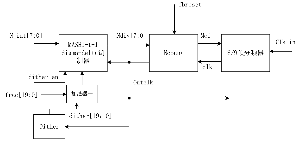
[0079] Below in conjunction with the accompanying drawings, the integer value of the input fractional N-frequency circuit is 8-bit integer value N_int[7:0], and the decimal value is 20-bit decimal value N_frac[19:0] as an example to further illustrate the present invention.

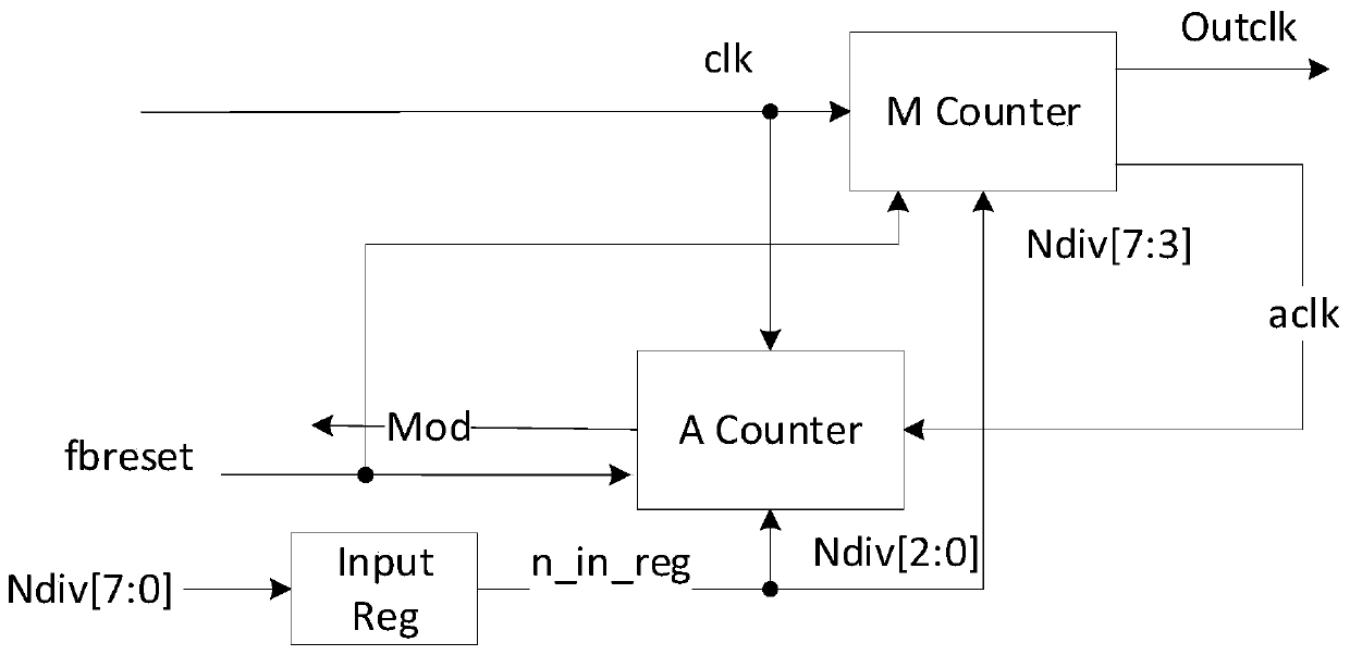
[0080] refer to figure 1 As shown, the fractional-N frequency division circuit applied to the frequency synthesizer provided by the embodiment of the present invention includes a MASH1-1-1 Sigma-delta modulator, a frequency division counting circuit Ncount, a pseudo-random sequence generation circuit Dither, and an adder- , Front 8 / 9 prescaler.

[0081] The input terminals of the MASH1-1-1 Sigma-delta modulator are respectively connected to the integer value N_int[7:0] and the output terminal of the adder 1, and the output terminal of the MASH1-1-1 Sigma-delta modulator is connected to the frequency division counting circuit Ncount The input terminal of the MASH1-1-1 Sigma-delta modulator is connected to...


PUM


Abstract

In order to solve the structure parasitic problem of a fractional frequency division circuit of a Sigma-delta modulator adopting a MASH1-1-1 structure, the invention provides a fractional N frequencydivision circuit and method applied to a frequency synthesizer. The fractional N frequency division circuit comprises a MASH1-1-1 Sigma-delta modulator, a frequency division counting circuit Ncount, afront P / (P + 1) prescaler, a pseudo-random sequence generation circuit Ditcher and an adder; the pseudorandom sequence generation circuit Ditcher is used for generating an n-bit pseudorandom sequenceand sending the n-bit pseudorandom sequence into the n-bit adder I; and the n-bit adder I is used for summing the small numerical value N _ frac [n-1: 0] received by the fractional N frequency division circuit and the n-bit pseudorandom sequence in each clock period, and sending a summing result corresponding to each clock period to the input end of the MASH1-1-1 Sigma-delta modulator.

Description

technical field [0001] The invention belongs to the technical field of frequency synthesizers, and relates to a fractional-N frequency division circuit and method applied to frequency synthesizers. Background technique [0002] When the RF chip is doing signal processing, the RF chip needs to filter, amplify, and down-convert the received signal, and then perform A / D conversion on the analog signal obtained by the down-conversion, thereby generating a digital signal that can be processed by the baseband circuit. The local oscillator frequency for down-conversion is generated by a frequency synthesizer after multiplying the reference frequency generated by a crystal oscillator, and in the frequency synthesizer, the frequency divider is the key to providing multiple high-precision frequency signals. The frequency divider in the traditional frequency synthesizer is an integer frequency division structure. In order to generate adjacent channel frequencies with small frequency in...

Claims


Application Information

Patent Timeline
Patent Type & Authority Applications(China)
IPC IPC(8): H03L7/18
CPCH03L7/1806Y02D30/70
Inventor 黄海生杨毅李鑫
Owner XIAN UNIV OF POSTS & TELECOMM
Learn More