Cross-flow type constant-temperature dehumidifying device

A technology of constant temperature dehumidification and cross flow, which is applied in the direction of heating, using air flow as shielding, household heating, etc., can solve the problem of desiccant performance degradation, and achieve the effect of simple structure

Active Publication Date: 2019-08-30
GUANGZHOU INST OF ENERGY CONVERSION - CHINESE ACAD OF SCI
View PDF9 Cites 5 Cited by
  • Summary
  • Abstract
  • Description
  • Claims
  • Application Information

AI Technical Summary

Problems solved by technology

[0005] In order to overcome the shortcomings of the above-mentioned prior art, the present invention provides a cross-flow constant temperature dehumidification device...

Method used


Image

  • Cross-flow type constant-temperature dehumidifying device
  • Cross-flow type constant-temperature dehumidifying device
  • Cross-flow type constant-temperature dehumidifying device

Examples


Embodiment Construction

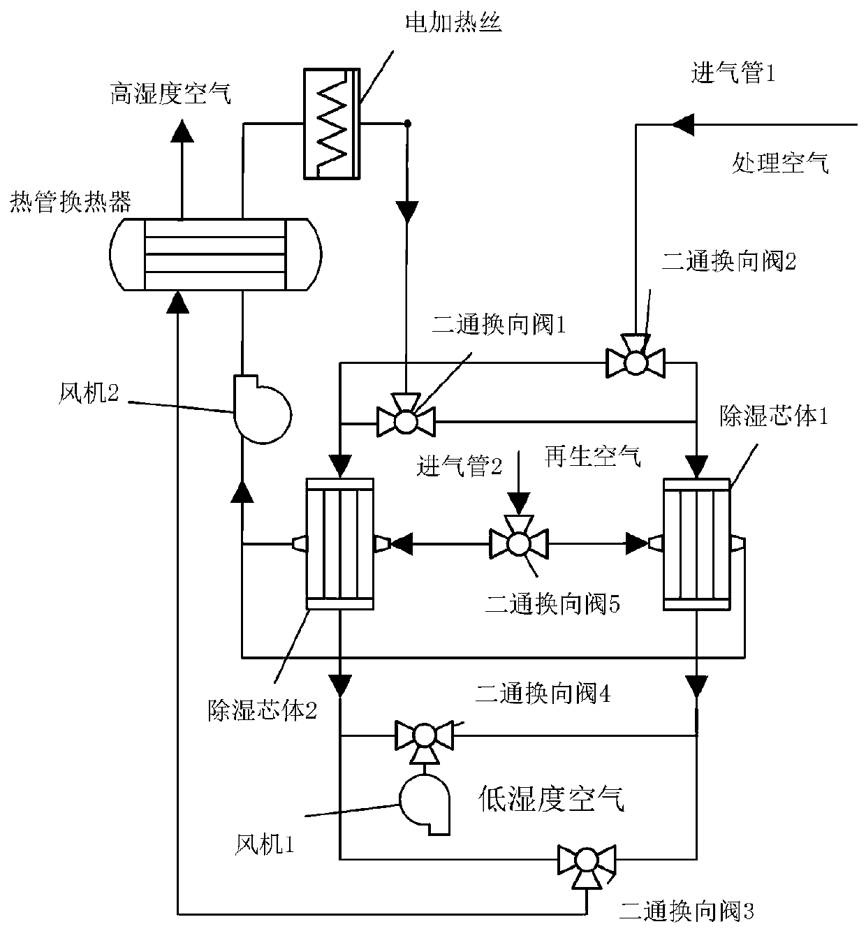
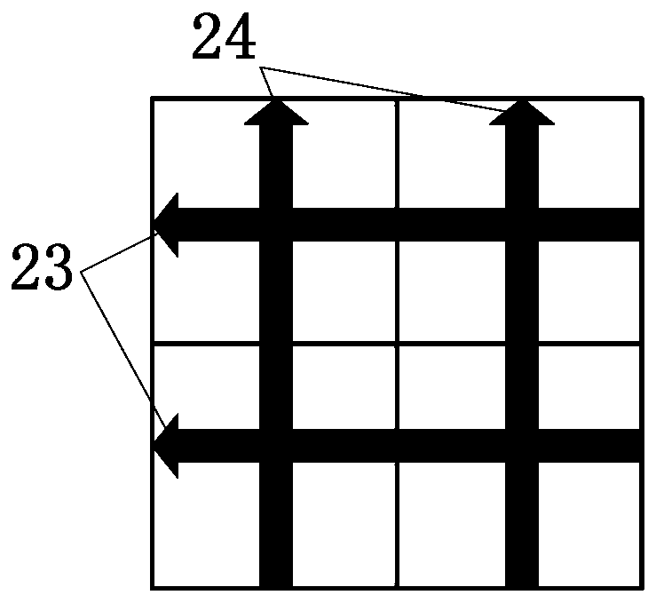
[0026] The cross-flow constant temperature dehumidification device of the present embodiment, such as figure 1 As shown, it includes an intake pipe 1, an intake pipe 2, a heat pipe heat exchanger, an electric heating wire, two-way reversing valves 1, 2, 3, 4, 5, fans 1, 2, and dehumidification cores 1, 2. The two dehumidification cores are cross-flow dehumidification cores with the same structure, each including a dehumidification channel and a constant temperature channel. The two channels are as follows: figure 2 , 3 As shown, it is distributed horizontally, vertically and vertically, 23 indicates a dehumidification channel, 24 indicates a constant temperature channel, 21 is a heat exchanger, and 22 is a desiccant coated on the surface of the dehumidification channel. The dehumidification channel is used to dry and dehumidify indoor humid air, the constant temperature channel is used to create a constant temperature environment for the drying and dehumidification process, ...


PUM


Abstract

The invention discloses a cross-flow type constant-temperature dehumidifying device. Two dehumidifying cores are adopted for alternately carrying out dehumidification and regeneration to obtain an uninterrupted dehumidifying effect. Adsorption heat is recycled, so that the problem that the performance of a dehumidifying agent is reduced due to the fact that the adsorption heat is accumulated in the dehumidifying cores and generates high temperature is avoided; and the adsorption heat generated in the dehumidification process is recovered by adopting air instead of liquid water, and the structure is simple, compact and light. The method for efficiently utilizing the low-grade waste heat is provided and accords with the strategic target of sustainable energy development, wherein the low-grade heat energy can be provided by solar energy, diesel flue gas waste heat, superheated steam exhaust steam and the like, and the application occasions of the adsorption type dehumidification technology are widened.

Description

technical field [0001] The invention relates to the technical field of dehumidification and energy saving, in particular to a cross-flow constant temperature dehumidification device. Background technique [0002] Air dehumidification units are widely used in food, pharmaceutical and other industries, as well as workshops, archives, museums, exhibition halls, laboratories and other places. At present, most dehumidification devices are mainly based on low-temperature condensation, and the system performance coefficient is not high. In contrast, another commonly used dehumidification method is solid adsorption dehumidification, which is in line with the development trend of industrial energy conservation and environmental protection in today's society. At present, the main device for solid adsorption is the dehumidification rotor, which has the advantages of simple structure, low noise, and long life. However, the treatment area of ​​the dehumidification rotor generates a larg...

Claims


Application Information

Patent Timeline
IPC IPC(8): F24F3/14F24F12/00F24F13/30
CPCF24F3/1423F24F3/1429F24F12/002F24F13/30F24F2012/005
Inventor 白羽邓立生黄宏宇何兆红窪田光宏李兴陈勇
Owner GUANGZHOU INST OF ENERGY CONVERSION - CHINESE ACAD OF SCI
Why Eureka
Try Eureka