Compensation table compression method, display manufacturing equipment and device with storage function

A compression method and compensation table technology, applied in the direction of static indicators, instruments, electrical components, etc., can solve the problems of occupying large system storage resources, time-consuming, high hardware system requirements, etc., to save hardware resources and reduce time-consuming , cost reduction effect

Active Publication Date: 2019-08-23
TCL CHINA STAR OPTOELECTRONICS TECH CO LTD
View PDF7 Cites 3 Cited by
  • Summary
  • Abstract
  • Description
  • Claims
  • Application Information

AI Technical Summary

Problems solved by technology

As the size of the display panel becomes larger and larger, the compensation table will occupy a large amount of system storage resources, which has high requirements on the hardware system, and the process of transmitting and burning data on the production line is time-consuming

Method used


Image

  • Compensation table compression method, display manufacturing equipment and device with storage function
  • Compensation table compression method, display manufacturing equipment and device with storage function
  • Compensation table compression method, display manufacturing equipment and device with storage function

Examples


Embodiment Construction

[0024] The following will clearly and completely describe the technical solutions in the embodiments of the present application with reference to the drawings in the embodiments of the present application. Obviously, the described embodiments are only some of the embodiments of the present application, not all of them. Based on the embodiments in this application, all other embodiments obtained by persons of ordinary skill in the art without making creative efforts belong to the scope of protection of this application.

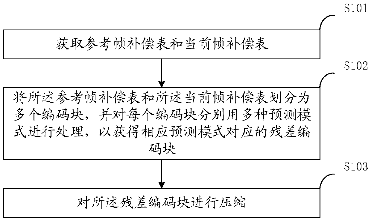
[0025] see figure 1 , figure 1 It is a schematic flow chart of the first embodiment of the compensation table compression method provided by the application, and the compensation table compression method provided by the application includes:

[0026] S101: Obtain a reference frame compensation table and a current frame compensation table.

[0027] In a specific implementation scenario, if the organic light emitting diode display panel contains compensation t...


PUM


Abstract

The invention discloses a compensation table compression method, display manufacturing equipment and a device with a storage function. The method comprises the steps of obtaining a reference frame compensation table and a current frame compensation table; dividing the reference frame compensation table and the current frame compensation table into a plurality of coding blocks, and processing eachcoding block by using a plurality of prediction modes to obtain a residual coding block corresponding to the corresponding prediction mode; and compressing the residual encoding block. By means of themode, resources can be saved, the cost is reduced, and the working efficiency is improved.

Description

technical field [0001] The present application relates to the display field, in particular to a compensation table compression method, a display manufacturing device and a device with a storage function. Background technique [0002] In order to eliminate the Mura of the display, a compensation table is usually used to store the compensation information of each pixel. When projecting images, the driver board looks up the compensation table, adjusts the signal, increases the signal in the dark area of ​​the panel, and lowers the signal in the bright area to present a uniform display effect. In the compensation table, each pixel corresponds to a set of compensation information, and each set of compensation information contains one or more compensation data. The physical meaning of the compensation data depends on the algorithm, usually the adjustment value of a specific gray scale, and some algorithms set it as the voltage value to be adjusted. [0003] The size of the compe...

Claims


Application Information

Patent Timeline
Patent Type & Authority Applications(China)
IPC IPC(8): H04N19/176H04N19/503H04N19/593H04N19/42H04N19/426
CPCH04N19/176H04N19/42H04N19/426H04N19/503H04N19/593G09G3/3208G09G2320/0233G09G2320/0285H03M7/3071H03M7/4031G09G2320/0242H03M7/30
Inventor 程琳
Owner TCL CHINA STAR OPTOELECTRONICS TECH CO LTD
Why Eureka
Try Eureka