
Battery pack heat dissipation device with centralized heat dissipation

A technology of heat dissipation device and battery pack, which is applied in the direction of batteries, secondary batteries, circuits, etc., which can solve the problems of general heat dissipation of batteries, failure of heat dissipation of batteries, and contact with battery electrodes, so as to avoid violent combustion or even explosion caused by thermal runaway , Improve the safety of use, and effectively dissipate heat

Pending Publication Date: 2019-08-23
FOSHAN UNIVERSITY
View PDF0 Cites 5 Cited by
  • Summary
  • Abstract
  • Description
  • Claims
  • Application Information

AI Technical Summary

Problems solved by technology

[0003] In the prior art, the phase change material is generally filled into the gap between the batteries or around the battery, but this method will cause a series of problems, 1. Some high thermal conductivity materials used to improve the thermal conductivity of the phase change material, such as metal Nanoparticles, metal foam, etc. are mostly good conductors. If the battery module is squeezed or the phase change material expands at high temperature, these thermally conductive materials are likely to contact the battery electrodes, resulting in a short circuit of the battery; 2. When the battery is used for a long time or When working under high discharge rate conditions, the melting rate of the phase change material is also increasing. When the phase change material is completely dissolved, the battery will not be able to dissipate heat.
Therefore, the power battery adopting the above-mentioned heat dissipation structure has a large volume, and the heat dissipation effect of the battery is average, which is likely to cause safety problems

Method used


Image

  • Battery pack heat dissipation device with centralized heat dissipation
  • Battery pack heat dissipation device with centralized heat dissipation
  • Battery pack heat dissipation device with centralized heat dissipation

Examples


Embodiment Construction

[0023] The present invention provides a battery pack cooling device for centralized heat dissipation. In order to make the purpose, technical solution and effect of the present invention more clear and definite, the present invention will be further described in detail below with reference to the accompanying drawings and examples. It should be understood that the specific embodiments described here are only used to explain the present invention, and are not intended to limit the protection scope of the present invention.

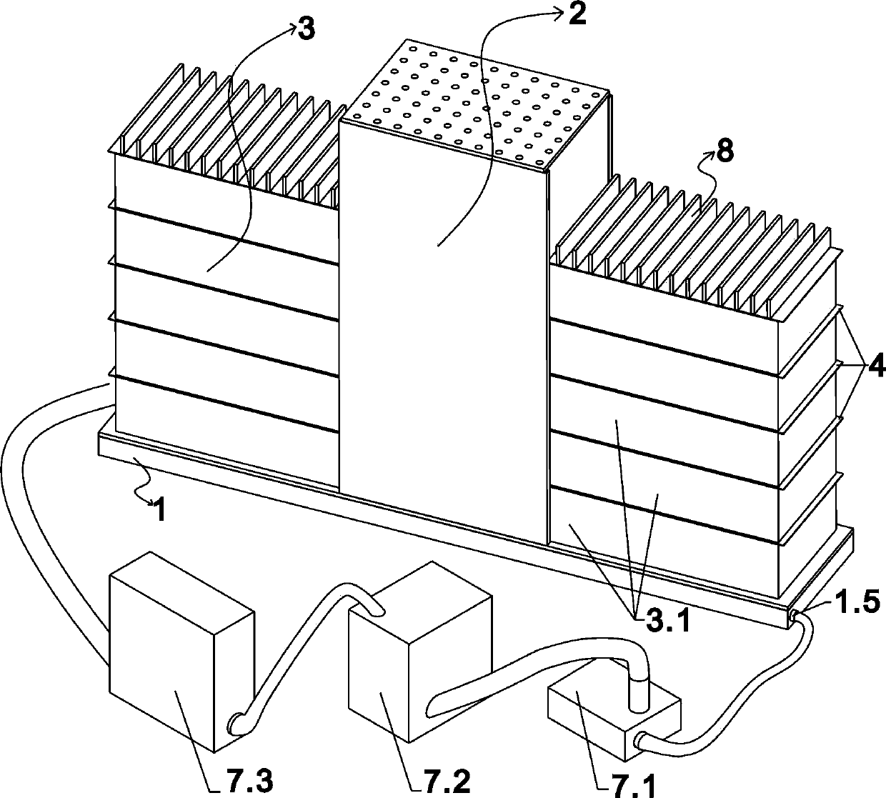
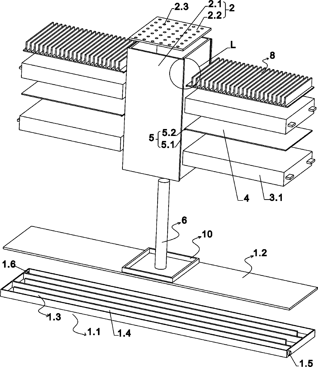
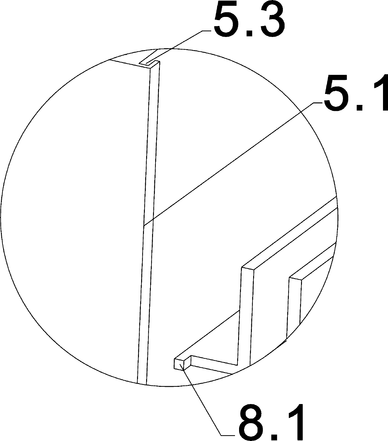
[0024] see Figure 1-Figure 2 , the present invention provides a battery pack cooling device for centralized heat dissipation, including a base 1, a cooling box 2 arranged on the upper end surface of the base, and several battery packs 3 (no more than 4). The inner cavity of variable material, each battery group corresponds to one side facing the heat dissipation box, the battery group 3 is formed by stacking a plurality of battery cells 3.1 in the vertical...


PUM


Abstract

The invention discloses a battery pack heat dissipation device with centralized heat dissipation, which comprises a base, a heat dissipation box and a plurality of battery packs, wherein the heat dissipation box and the plurality of battery packs are arranged on the upper end face of the base, the heat dissipation box is provided with an inner cavity for filling a composite phase change material,each battery pack correspondingly faces towards one side surface of the heat dissipation box, the battery pack is formed by stacking multiple single batteries along the vertical direction, two adjacent single batteries are provided with a heat conducting sheet therebetween, the heat conducting sheets are in heat conducting connection with the outer side wall of the heat dissipation box through a positioning mechanism, and the end face, which faces towards the heat dissipation box, of each single battery is in heat conducting connection with the outer side wall of the heat dissipation box. Compared with the prior art, each single battery in the power battery conducts heat to the heat dissipation box filled with the composite phase change material for heat dissipation in a centralized mannerthrough the heat conducting sheet, thereby improving the heat exchange rate of the battery pack, and playing a good heat dissipation effect for the single batteries. The composite phase change material is reasonably utilized, the melting and leakage of the composite phase change material are avoided, and the use safety is improved.

Description

technical field [0001] The invention relates to the technical field of power vehicle batteries, in particular to a battery pack cooling device for centralized cooling. Background technique [0002] The power battery is usually used as the energy source of electric vehicles, and its heat dissipation system is related to the safety of the battery. The distribution characteristics of the battery temperature not only affect its conversion efficiency and life, but also affect its safety. [0003] In the prior art, the phase change material is generally filled into the gap between the batteries or around the battery, but this method will cause a series of problems, 1. Some high thermal conductivity materials used to improve the thermal conductivity of the phase change material, such as metal Nanoparticles, metal foam, etc. are mostly good conductors. If the battery module is squeezed or the phase change material expands at high temperature, these thermally conductive materials are...

Claims


Application Information

Patent Timeline
Patent Type & Authority Applications(China)
IPC IPC(8): H01M10/613H01M10/625H01M10/647H01M10/6555H01M10/659H01M10/6556H01M10/6568H01M10/655H01M10/6551
CPCH01M10/613H01M10/625H01M10/647H01M10/6555H01M10/659H01M10/6556H01M10/6568H01M10/655H01M10/6551H01M2220/20Y02E60/10
Inventor 张文灿凌国智邱洁玉梁志成
Owner FOSHAN UNIVERSITY
Learn More