Vascular implant, conveying device and medical equipment
A delivery device and implant technology, applied in the field of medical devices, can solve problems such as inability to stably transport vascular implants, difficulty in controlling the magnitude of friction, and unloading of vascular implants, so as to reduce the difficulty of surgical operations , Locking and unlocking operation is convenient, and the effect of improving safety
- Summary
- Abstract
- Description
- Claims
- Application Information
AI Technical Summary
Problems solved by technology
Method used
Image
Examples
Embodiment 1
[0098] Such as Figure 4 As shown, in this embodiment, the delivery rod 4 includes a second connecting portion, the second connecting portion includes at least two second connecting pieces 3, and the at least two second connecting pieces 3 are spaced apart in the axial direction of the rod body ground setting. Assuming that there are two second connecting pieces 3 , the axial distance between the two second connecting pieces 3 is configured to allow engaging at least one first connecting piece 2 . Since the first connecting piece 2 can be an elastic member, it can be compressed between the two second connecting pieces 3, so the axial distance between the two second connecting pieces 3 can be less than or equal to the first connecting piece 2 The axial length (that is, the length before compression). However, the first connector 2 can also be a rigid member without elasticity, that is, non-deformable. At this time, the axial distance between the two second connectors 3 can be...
Embodiment 2
[0105] Such as Figure 7 with Figure 8 As shown, in this embodiment, the second connecting part of the delivery rod 4 includes at least one second connecting part 3, while the first connecting part of the proximal end 11 of the support 1 includes at least two first connecting parts 2, at least The two first connecting parts 2 are arranged at intervals along the axial direction at the proximal end of the stent 1 . Below it is assumed that there are two first connectors 2 . The axial distance between the two first connecting pieces 2 is configured to allow at least one second connecting piece 3 to be engaged. Here, the axial distance between the two first connecting parts 2 may be greater than the axial length of the second connecting part 3, or less than or equal to the axial length of the second connecting part 3, for example, the first connecting part 2 is an elastic member , can be stretched or compressed.
[0106] Such as Figure 9 As shown, in actual operation, in the ...
Embodiment 3
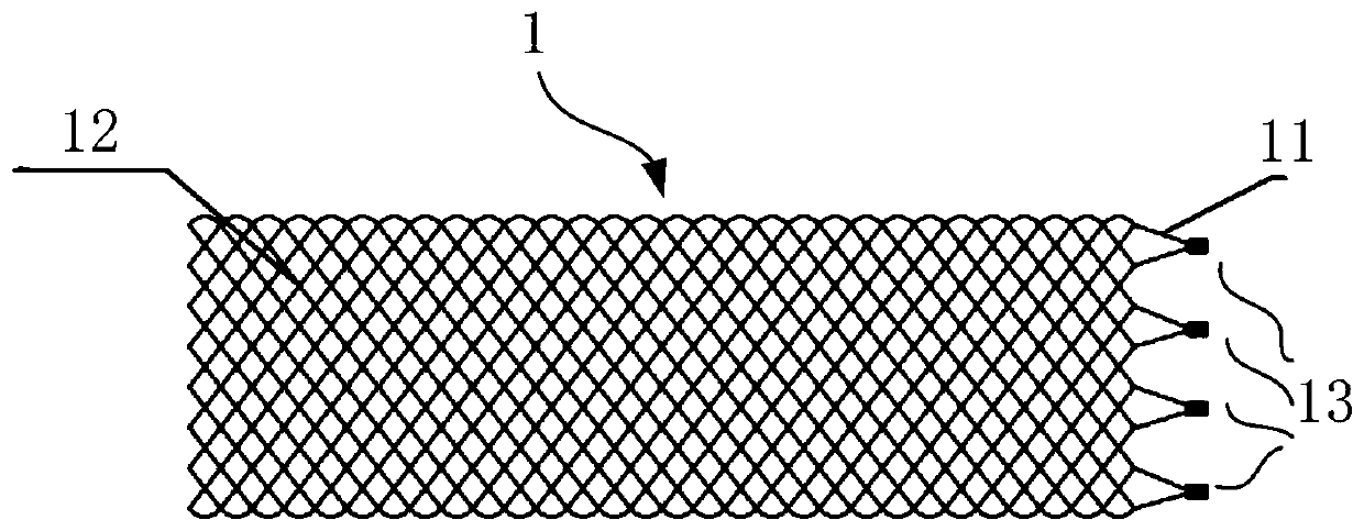
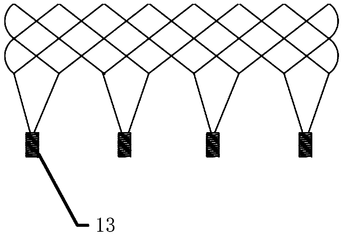
[0109] In this embodiment, the first connection portion at the proximal end of the stent includes more than two first connection groups, and more than two first connection groups are arranged at intervals along the axial direction of the stent 1, and each first connection group includes two Above the first connecting piece 2, more than two first connecting pieces 2 in each first connecting group are arranged at intervals along the axial direction of the bracket 1, and the buckle 13 in the same first connecting group is on the bracket 1 aligned axially. Axially aligned means that, on the same projection plane perpendicular to the axis of the bracket, the axial projections of the buckles 13 in the same first connection group are coincident.
[0110] Further, the inventors found that when the radial dimension of the first connecting member 2 is relatively large, or the number of buckle members 13 is large, the compressed size of the stent 1 and its delivery device is too large. ...
PUM
 Abstract
Description
Claims
Application Information
 - Generate Ideas
- Intellectual Property
- Life Sciences
- Materials
- Tech Scout
- Unparalleled Data Quality
- Higher Quality Content
- 60% Fewer Hallucinations
Browse by: Latest US Patents, China's latest patents, Technical Efficacy Thesaurus, Application Domain, Technology Topic, Popular Technical Reports.
© 2025 PatSnap. All rights reserved.Legal|Privacy policy|Modern Slavery Act Transparency Statement|Sitemap|About US| Contact US: help@patsnap.com


