Ultrasonic-guided visualized positioning device for animal in-vivo blood vessel and method

A positioning device and animal body technology, applied in stereotaxic surgical instruments, trocars, medical science, etc., can solve the problems of tissue deviation, experimental failure, and difficulty in establishing a repeatable standardized experimental animal injury model, etc. Achieve the effect of precise injury location and avoid uncertainty

Pending Publication Date: 2019-08-23
FIRST HOSPITAL AFFILIATED TO GENERAL HOSPITAL OF PLA
View PDF11 Cites 2 Cited by
  • Summary
  • Abstract
  • Description
  • Claims
  • Application Information

AI Technical Summary

Problems solved by technology

For example, when the depth of injury is 100mm, the deviation of the incident angle of 10° will cause the bullet to deviate from the expected track by 17mm. causing the experiment to fail
[0009] (2) The animal body surface is soft tissue, body position adjustment will affect the accuracy of notch line marking
Remember that after the line marking is completed, the position of the experimental animal will change when the positioning is adjusted, and the epidermis and internal tissues of the experimental animal will deform with the change of force, resulting in a change in relative position, causing the tissue to be injured to deviate from the incision line Mark the position, even if the position of the anterior notch line is accurately marked, it will deviate due to positioning adjustment, making it difficult to establish a repeatable standardized experimental animal injury model

Method used


Image

  • Ultrasonic-guided visualized positioning device for animal in-vivo blood vessel and method
  • Ultrasonic-guided visualized positioning device for animal in-vivo blood vessel and method
  • Ultrasonic-guided visualized positioning device for animal in-vivo blood vessel and method

Examples


Embodiment Construction

[0047] The technical solutions of the present invention will be clearly and completely described below in conjunction with the accompanying drawings. Apparently, the described embodiments are some of the embodiments of the present invention, but not all of them. Based on the embodiments of the present invention, all other embodiments obtained by persons of ordinary skill in the art without making creative efforts belong to the protection scope of the present invention.

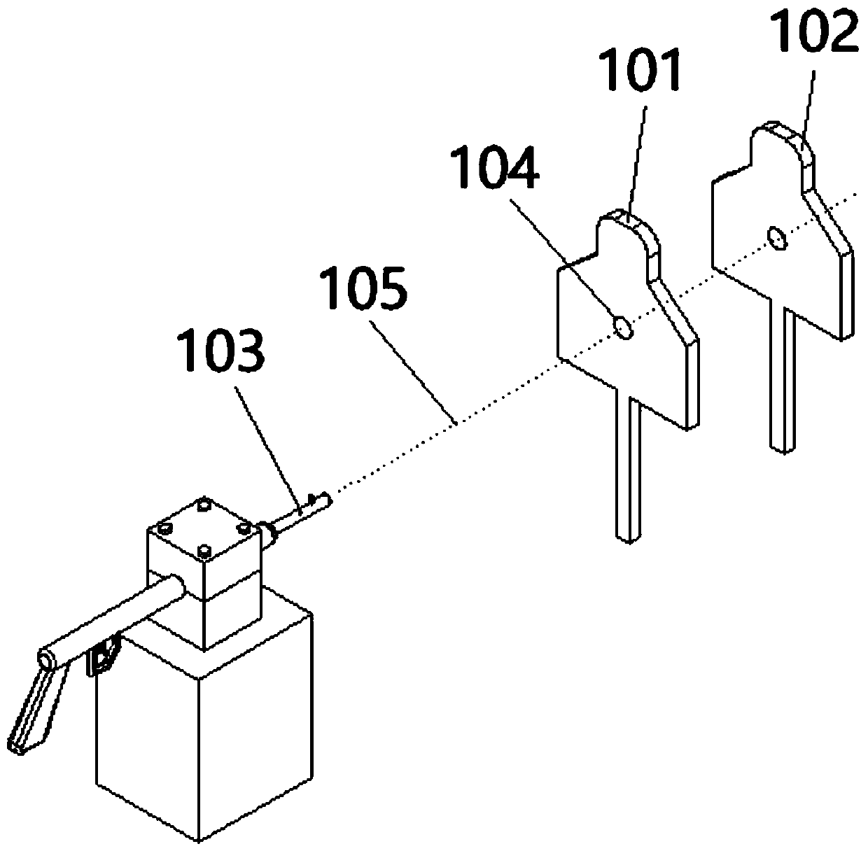
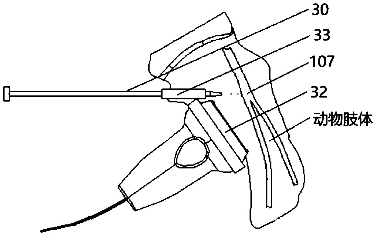
[0048] A device for visualization and positioning of blood vessels in animals under the guidance of ultrasound, such as Figure 4 As shown, it includes an ultrasonic diagnostic instrument 31, an ultrasonic probe 32, a puncture guide frame 33, a laser positioning device and a puncture needle 30. The ultrasonic probe 32 is electrically connected to the ultrasonic diagnostic instrument 31, and the puncture guide frame 33 is installed near The working end of the ultrasonic probe 32; the laser positioning device in...


PUM


Abstract

The invention relates to an ultrasonic-guided visualized positioning device for an animal in-vivo blood vessel. The ultrasonic-guided visualized positioning device comprises an ultrasonic diagnostic apparatus, an ultrasonic probe, a puncture guide frame, a laser positioning device and a puncture needle, wherein the ultrasonic probe is electrically connected with the ultrasonic diagnostic apparatus, and the puncture guide frame is mounted at a working end close to the ultrasonic probe; the laser positioning device comprises a supporting frame, the top end of the supporting frame is sequentiallyconnected with a laser, a first locating ring and a second locating ring from left to right, horizontal-penetrative collimating locating holes are separately formed in dead centers of the first and second locating rings, and a laser position line emitted from the laser penetrates through the collimating locating holes and a shot hole; the puncture needle is mounted at the bottom end of the supporting frame, the front end, close to a spine, of the puncture needle is mounted in a locating groove of the puncture guide frame, and the laser position line is parallel to the axis of the puncture needle. According to the device, an angle of incidence of a shot can be accurately determined, and the accurate positioning of a wound to an experimental animal caused by the shot is ensured.

Description

technical field [0001] The invention relates to the technical field of animal wounding experimental devices, in particular to a device and method for visually positioning blood vessels in animals under the guidance of ultrasound. Background technique [0002] When studying the on-site hemostasis or wound repair of gun penetrating wounds or blind wounds, ballistic guns are often used to accurately wound specific tissues in animals, such as organs or blood vessels, to simulate the wounding effect of specific parts of the human body under battlefield or anti-terrorism conditions. Establish a standardized animal injury model as the basis for the structural design and effect evaluation of hemostatic materials and hemostatic devices. [0003] When wounding the outer surface of experimental animals, the shooting accuracy and repeatability of ballistic guns are good. In order to establish a standardized animal injury model and realize the precise injury location of bullets, experime...

Claims


Application Information

Patent Timeline
IPC IPC(8): A61B90/13A61B90/11A61B17/34
CPCA61B90/13A61B90/11A61B17/3403A61B5/489A61B2090/378A61B2017/3413
Inventor 帅万钧晁勇李振彩乔龙学张少东董灿高华永
Owner FIRST HOSPITAL AFFILIATED TO GENERAL HOSPITAL OF PLA
Why Eureka
Try Eureka